or single ended emitter follower.
http://www.diyaudio.com/forums/solid-state/239418-tgm7-amplifier-based-greg-ball-ska.html
Sure! 🙂
I've done a lot of thought about a current sensing bias circuit. I've even started a simple embedded circuit to sense current and control bias and provide protection. The one goal is to have no initial setup. The project died a while ago - the bias spreader is just simpler and works perfectly.
Hi Guys
mrcloc: Why do you use current mirrors as current sources rather than the 2-BJT feedback-controlled circuit? The latter is faster and you are using two BJTs anyway. I don't think the loss of 700mV in the feedback version is worth considering - that would mean you are clipping the amp.
Many designers view current sources/sinks as being "not part of the audio path" but they are mistaken. Those circuits are providing the 'push' or the 'pull' against a single-ended VAS or other stage, so their speed is just as important as the signal-driven half.
Also, if you use the mosfets in a CFP-style circuit with slight gain, then the gate voltage is no longer in series with the output voltage so the only loss is over R-ds.
Also: Mouser and Digikey are US vendors that ship worldwide and process orders in various currencies. Check them out. They carry many of the 2SA-2SC pairs and similar Fairchild FSA-FSC parts. They are reputable and work hard to deal only with legitimate suppliers.
Hi. Thanks. I didn't know the feedback controlled current source is faster. I definitely consider speed important in the current source, hence why I want lower power in the VAS; so I can use small signal transistors. I understand there are bigger transistors that are fast too, but then you deal with much lower Hfe, and you need a similar transistor for the amplifier where Hfe is important, etc.
I'll try the different current source. In the LTP, I've changed the current source for one transistor with a zener.
I will definitely investigate CFP style configuration. Isn't that exactly how IGBTs work?
I like Mouser and Digikey - good to know they do well to stock genuine stuff. I know the manufacturers list them. The only thing is that shipping is very expensive. I'll check it out today.

No - heck! Shipping is R600 minimum, unless you buy over R2000. I'll buy for over R2000 at some point, and then I can get some stock, but for now, the expensive shop down the road will have to do.
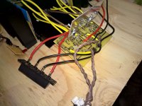
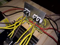
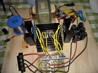
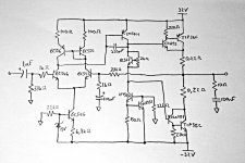
So the evolution of this amplifier has been built. The PCB needed 3 modifications, very minor, but it does look a little bit of a mess. Not too bad - all can be incorporated on this layout in the future. Here it is with no Darlingtons, and the outputs are some old TIP35/6's I had. I'll do some measurements, but I don't think I'll replace the TIP's with anything else. For future amps, I'll decide based on this one's performance.
So far, it sets up as expected. Dead silent; no hum, very low noise. I'll have to see if I can hear noise, but I'm not 100% sure how I can do this. No input makes it buzz a little, and with an input, all I can hear is the quantisation noise of my phone / CD player. I'll have to use a higher quality source.
I'll measure it, but currently it's only set up to 25 mA. I believe this should be fine. The driver heatsink is quite big, so thermal feedback is slow. Total quiescent varies from 62 mA to 66 mA very slowly, but once it's warmed up it's rock solid and holding the heatsink doesn't make much difference.
As it is here, it can accept +-50 V. The VAS transitors might need a small sink, but that's all. With that sort of voltage, 2 or 3 pairs of output transistors are needed with I'd say 0.22 ohm emitter resistors.
There is barely a turn on noise, and it just fades out on turn off - no thump.
I must say thanks for the comments here! Struth, that current source is excellent.
I'll post the measurements of this and the Darlington version as soon as I have some.
Attachments

Hi Guys
Now all you need to do to knock THD down an order of magnitude is to add an EF to the VAS. This is very simple to do inasmuch as it makes the VAS look ALMOST like a Darlington except that the collector of the input transistor is tied to ground rather than to the collector of the existing VAS. dd a 1k to 2k2 across the BE of the VAS.
I also place a resistor from the amp output to ground, usually 1k, to assist in turn-on/off settling. Depending on the power output of the amp this R might have to be a power type. With 50V rails, it should be a 3W.
There are other details that can be improved in the design and these can be done in any order or combination:
Diff-amp degeneration: Some say this is important others say not. if you add the emitter Rs to the diff amp, the compensation cap will need reducing in value to maintain stability.
Input section decoupling: On the VAS suply rail, a series R is added between the output stage and VAS/diff-amp feed, and a cap to ground is added on the VAS-side of this R. R is typically 22-330R depending on the currents needed for the front end. C should be 220uF or higher, modern amps use 1mF.
Lower-value Rs for lower noise: The feedback loop Rs and the input base-leak and base-stop are often made much lower in value to reduce thermal noise (hiss). If you changed the 33ks to 10k, then change the 1ks to 303R, the gain will be the same but noise is reduced about 1.7 times. if you reduced the values by 10x then noise would be cut by more than half. When you do these R changes, you have to bump up the C values by the same factor.
LF rolloff: The 100uF cap in the feedback loop is a joke even for an amp that is to drive only tweeters. This cap should roll off in the sub-1Hz range so that its distortion is not significant in the audio band. A simulation of your circuit will show that changing from 100uF to 1mF then to 10mF causes reduced THD at 1kHz. This cap is a low-voltage part so high values do not make it a large part.
Have fun
Thank you Struth, some valuable input there.
I understand specifications-wise there can be value to everything you've suggested, or at least to some combination or some variation thereof. At the moment, PSRR is very high - hum is inaudible. Turn on sometimes has a very slight click, but you have to be listening out for it. Turn off has absolutely no thump whatsoever. It just fades away. In fact, quiescent current remains about 64 mA until some point where it just drops to 0. THD I'm expecting in the region of 0.005%. To implement such a lot of extra bits and pieces, and to experiment which combination gives the best results is a bit too time consuming for me at the moment, especially since the improvement will really be minimal (having a newborn around doesn't help).
As I said, hum is basically gone. At 2am when there isn't a sound to be heard, if you really listen for it with the speaker on your ear you can maybe make out a touch of hum. I haven't heard any noise (hiss) yet - the input device's hiss is far louder, and I haven't completed construction: when there is no input there is still a dash of buzz. I need to earth the amp, test the output noise and hum, and sort out the input.
I completely agree that the 100uF is a bit too small. 220uF would have been 100's. But I don't think there will be any reduction in THD changing this cap. I may be wrong. The 100uF does about 5Hz, which I think is fine, but my input capacitor changed unexpectedly to a 1uF (should have been 560nF but the shop didn't have), so the 100uF is unfortunately the limiting capacitor (the input cap and feedback cap have poles almost exactly the same at about 5Hz).
The only improvement I would really suggest is to use BC550/560 rather than BC546/556 (provided the supply does not exceed +-42 V). And if the supply is kept to <+-30V, I would make the VAS transistors BC546/556, but keep the BC547 in the bias control. This will ensure that noise is kept to an absolute minimum. If you want to stick your nose in the air, use a more "suitable" pair of output transistors too.
The resistors are all 0.5 W metal film, and I would suggest nothing less. I've tried to compromise to keep all resistor values small, and then having a decent input resistance. 33k is the biggest value, and this is fairly small still. The bigger metal film resistors make a huge difference.
Last edited:
I can't measure hum and noise. My oscilloscope's noise drowns it out and I see no change when I connect my amplifier output. The quantisation noise of my sources drowns everything out. I added an RF capacitor (220pF) in parallel with the input grounding resistor (33k). I need a better oscilloscope probe. Do CFLs emit high frequency? I think my scope is picking up the close by CFLs noise.
Uh, yes, CFL's emit some RF. So do lamp dimmers, cell phones, television with digital technology, PCs.
I saw your wood platform chassis and was thinking "my, SAfrica must be a very RF free environment." Well, maybe not.
My experiments are going on in a used amp chassis, which is a bathtub of steel the new electronics sit in. Only the top is open to probing. The PC, Television, digital toys etc are in another room.
For my next amp, I've been picking up used steel file boxes, which are totally enclosed with a hinged top. About $4 in charity resale shops in trash rich USA. I imagine in a country full of poor imigrants, the option of picking up good trash enclosures will not be so apparent. Perhaps you could experiment in old VCR chassis, which are reviled but were built in steel chassis. Or perhaps an old microwave oven, which are inherently RF shielded. At worst case you could build in an old PCAT tower case or something.
I do okay experimenting with one wall of the steel bathtub(the top) open. But when I check noise, I drive the amp with a PAS2 which has TWO enclosures inside to keep the nasty RF from the high gain electronics, connected to my amp with a shielded RCA cable. Alternately I drive my amp with a heavily modified RA88a mixer, which I went to great pains to screen RF out of since it came so wimpily vulnerable to interferance. The basic mixer steel box was okay, but barking dogs yelping out "Dixie" on the CB channel were annoying me greatly. See this thread about all I did to keep RF out of the RA88a chassis. http://www.diyaudio.com/forums/anal...improving-disco-mixer-mid-fi-performance.html
Basically, RCA jacks isolated from the safety grounded steel case by rubber o-rings. 33 pf disk caps from inputs to analog ground. Toroid hash filters from PCAT power supplies on the DC power coming in. AC transformer outside the mixer case, a wall-wart.
Real amp shops have "faraday cage" testing rooms to check the prototypes in. I saw one at college in the space science department. copper screen around a whole room, with ground wires soldered on and taken to a central junction to the safety ground. I can't afford that. I can afford some scrap steel enclosures. I just built a nice cover for an organ diode summing board, out of steel mesh from the builders supply with 3 mm holes, $8 a 4'x8' sheet. I cut a 4 lip blank with shears. Then I bent it into a box cover with a c-clamp, a steel box beam as an anvil, and a couple of hammers. I closed the box with loops of steel picture hanging wire, and spray painted it black to draw the eye away from it.
Or your can spend $$$ on a real chassis from e-bay. Way too rich for my budget. Happy scrap hunting.
As far as struth's quibbles, I don't have sim technology (I run ubuntu op system) but I wonder if he is trying to get your amp from .005% hd to .0005? IMHO I'll never hear even .005% on speakers. Even with my frequently protected ears that were tested okay to 14000 hz in 2008. My ST120 with djoffe idle current control sounded equivalent to my $1000 CS800s spec'ed at .02% hd, even though people called the ST120 the worst amp on earth. Just, I couldn't keep the djoffe board from blowing sense transistors and going open loop 250 ma idle current in the OT's.
BTW, I don't measure HD and IMD. I try my amps out against the real Steinway piano located between the speakers. No speaker was close in sound until I found the SP2-XT at $600 the pair. On piano source disk, the ST70 amp is not close to real, even with new e-caps, output tubes, new plate caps and new metal film resistors over 100k. The ST120 was **** as originally designed. After the djoffe bias mod, it sounded pretty good. Also the CS800s sounded great, when it actually works (which is rare, switcher supply needs work I think, it trips the breaker). My test record is the top octave solo piano part of Peter Nero, Young & Warm & Wonderful. ST70 was fuzzy at best, as was the unmodified ST120. When everything preamp/amp is right, the vibrato on the Steinway goes away, and there are nice clear pings. Pianos do not make vibrato, that is HF IM distortion IMHO. George Winston Wyndam Hill albums are also great piano source disks, very hard to reproduce on speakers. Happy listening.
Last edited:
Thank you Indianajo. I really enjoyed reading your post!
I was measuring about 50 kHz, but I measured it with the scope leads disconnected, so I assume it's the CFLs, or some other RFI. Cool thing is that after I added the RF capacitor on the input, the input was far less sensitive to it to the point that I couldn't see it on the amplifier output. Very happy about that!
Don't forget - South Africa were world leaders in RF technology not too long ago... 😉 Anyway, yes, RFI is a problem everywhere in the world. Coincidentally, my two amplifiers I'm using for my home system have wooden enclosures. RFI is no problem. I like the wooden finish - I'll post some pics of my 135W main amp sometime (I actually planned to line the inside of the box with foil, but I was too lazy). Anyway, it was the oscilloscope leads picking up the bulk of the RF. 🙁
Fantastic idea about looking for an old enclosure and revamping it. Metal ones aren't too expensive here, but if I can recycle one, that will be great. The video machine idea is great! There are a number of places I can find old metal enclosures. For this amplifier I built now, I want it in a metal box, but I want the top panel to be a mesh, much like what you talk about, since the heatsinks are in the middle of the layout, and they're the bulk of the floor area.
I want to find those piano parts - I'm keen to listen to them on my main system. Thanks!
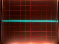
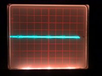
I've done some measurements on my amp in #106. Got a new scope probe to do this. In the pics, the first one is anything <2ms, the second is at 5ms. Both are at my scope's limit at 5mV/div. I think I've calculated it correctly. SNR = 100dB. I really don't know the calculations, or if I can even measure what I need. I'll read about standard ways to measure SNR.
Either way, i can't see hum, i can't hear hum with my ear on the speaker, and it's midnight and everyone's asleep and we live in an exceptionally quiet area. I can't hear noise, and it looks like it's peaking at 1mV. Turn on occasionally makes a very quiet click, turn off has no thump, only sudden fade out when the rails drop below a certain level. I'm extremely happy.
I've been working for years improving on previous designs. Since my first amp, I've been working on the turn on and off thump. I got that to an acceptable point, and for a short while I've been focusing on hum, and I decided to have a go at lowest noise possible for this design. So now I have those boxes ticked.
Next up: Non-intrusive amplifier and speaker protection. I'll measure the performance of this amp when I get a chance (need quite a setup), but I'm confident it will be a good one.
Attachments
I saw a small oscillation on the output into a reactive load, so I bypassed the current source in the VAS with a 470pF.
So to confirm, the SNR is somewhere between 97 dB and 100 dB (calculated). The noise RMS value is about 303 uV. I think that's pretty good for a 55 W amplifier.
I target <0.1mVac for Hum+Noise at the speaker terminals.
0.3mVac is my absolute top limit for all amplifiers that I build even a 170W Leach.
D.Self suggests even lower. -96dBu if I remember correctly for a 100W amplifier.
0.3mVac is my absolute top limit for all amplifiers that I build even a 170W Leach.
D.Self suggests even lower. -96dBu if I remember correctly for a 100W amplifier.
Last edited:
I target <0.1mVac for Hum+Noise at the speaker terminals.
0.3mVac is my absolute top limit for all amplifiers that I build even a 170W Leach.
SNR difference between 0.1 mVac and 0.2 mVac (more or less 100 dB SNR for this amp) isn't really all that much. Both are essentially silent. I'm quite happy with 0.3, to be honest (and that's the highest value possible, it's more likely 0.2). What I do know is that this doesn't increase for a higher power amplifier... 🙂 So I'll get to the >150W mark sometime (and then I'm in 108 dB SNR territory), but I don't need it, and it doesn't serve my purpose right now.
So I haven't had much time since I last posted here. Things got quite busy for me having a new baby come into the world. 🙂
I promised I would reach the title, and so I have. I haven't built it yet, but I built the exact design for a 55W in 8 ohms some time ago (pictured in post #106), and it's been in great use for the last few months.
I gave it to a friend while I tried to quieten his Gainclone based amp I built him a while ago. He's got a pair of Q Acoustics 2020i's, each rated at 6 ohms. The 55 W would have been capable of 75 W easily, and he said he left the amp on for extended periods, and drove his speakers quite hard. He did all his TV through the amp. He also said it's got a great quality to it, and it's dead silent. He's quite a perfectionist, and he couldn't hear a sound, unless he was watching a movie or listening to music.
So anyway, I've since used it to power 4 ohm speakers. I got excellent results with those as well, so it's looking great.
I had a bit of time now to investigate the possibility of higher power with the same design, and it's most definitely capable of 640 W in 4 ohms with a +- 78 V power supply. I just can't build one yet, simply because I don't have the money at the moment. It will cost a bit to build. Probably R4000 per board (that's about $300), and then it's about R2500 for the power supply ($180). Then I need to still build it into an enclosure, etc.
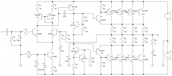
Ok, so I've designed the 135 W thing. It's going to be a 150 W / 8, 300 W / 4. 135 W is conservative. It will use a +- 51 V supply to get this. I have attached the design. The bias control needs only a 2k trimmer, with the base of Q6 in the middle. I've found this setup to work the best. I've designed a bias control to have two 560 ohm resistors, one on each side of the trimmer, and use a 1k trimmer. But I don't think it's worth it if you use a 10 turn pot. For this sort of power, TIP35/6 will work as output devices. And very well too.
Out of interest, for using +-78 V supply, the output needs to be doubled (8 pairs per amp), and for 4 ohm capability, there needs to be one 0.6 K/W heatsink per 8 output transistors. For only 8 ohm capability, one 0.6 K/W for all 16 output transistors will do fine.
I promised I would reach the title, and so I have. I haven't built it yet, but I built the exact design for a 55W in 8 ohms some time ago (pictured in post #106), and it's been in great use for the last few months.
I gave it to a friend while I tried to quieten his Gainclone based amp I built him a while ago. He's got a pair of Q Acoustics 2020i's, each rated at 6 ohms. The 55 W would have been capable of 75 W easily, and he said he left the amp on for extended periods, and drove his speakers quite hard. He did all his TV through the amp. He also said it's got a great quality to it, and it's dead silent. He's quite a perfectionist, and he couldn't hear a sound, unless he was watching a movie or listening to music.
So anyway, I've since used it to power 4 ohm speakers. I got excellent results with those as well, so it's looking great.
I had a bit of time now to investigate the possibility of higher power with the same design, and it's most definitely capable of 640 W in 4 ohms with a +- 78 V power supply. I just can't build one yet, simply because I don't have the money at the moment. It will cost a bit to build. Probably R4000 per board (that's about $300), and then it's about R2500 for the power supply ($180). Then I need to still build it into an enclosure, etc.
Ok, so I've designed the 135 W thing. It's going to be a 150 W / 8, 300 W / 4. 135 W is conservative. It will use a +- 51 V supply to get this. I have attached the design. The bias control needs only a 2k trimmer, with the base of Q6 in the middle. I've found this setup to work the best. I've designed a bias control to have two 560 ohm resistors, one on each side of the trimmer, and use a 1k trimmer. But I don't think it's worth it if you use a 10 turn pot. For this sort of power, TIP35/6 will work as output devices. And very well too.
Out of interest, for using +-78 V supply, the output needs to be doubled (8 pairs per amp), and for 4 ohm capability, there needs to be one 0.6 K/W heatsink per 8 output transistors. For only 8 ohm capability, one 0.6 K/W for all 16 output transistors will do fine.
Attachments
Congratulations on a silent amp that holds up for months in the hands of an appreciative user. Maybe not commercially silent, but if you & he can't hear it, who cares?Things got quite busy for me having a new baby come into the world. 🙂
I promised I would reach the title, and so I have. I haven't built it yet, but I built the exact design for a 55W in 8 ohms some time ago (pictured in post #106), and it's been in great use for the last few months.
I had a bit of time now to investigate the possibility of higher power with the same design, and it's most definitely capable of 640 W in 4 ohms with a +- 78 V power supply. I just can't build one yet, simply because I don't have the money at the moment. It will cost a bit to build. Probably R4000 per board (that's about $300), and then it's about R2500 for the power supply ($180). Then I need to still build it into an enclosure, etc.
Ok, so I've designed the 135 W thing. It's going to be a 150 W / 8, 300 W / 4. 135 W is conservative.
About the R2500 for the power supply for the high power amp. If you have more time than money, maybe not with a new child but: Switcher supplies are going to the dump every day masked as televisions and other appliances. Big switcher FETs, large toroids with fat wire, entire driver setups with coils and such. I picked up a monster couple of boards out of a 50" sanyo LED TV last summer. In your country you'd have to make the acquaitance of a salvage truck operator, but you should be able to pay a lot more than the copper recycler. Say $10 a board.
Most devices are down converters, 400 VDC to 15 VDC or something, but one can pull windings off the toroid and monkey with the resistor values of the control circuit. Something I'm comtemplating in the cold winter as I need a 12vdc to 24DC circuit to control valves on my car. Of course any RF device needs to be in a steel box of its own separate from audio gear.
Also those huge TO3-p NFETS could possibly be used for an amp if the design was proper. I scored about 11 IXTK62n25 fets and about 10 1.5"x3"x.75" heat sinks with this find. No depletion or pfets though.
The days of junction power transistors from salvage are over, I'm afraid. I still have a 48 vdc lambda supply upstairs harvested 198x that might yield some BJT's plus the transformer. But I'm retired and was around in the day of BJT's.
Watch the using two hands probing thing, 200 vdc or 400 vdc is seriously dangerous.
Last edited:
Congratulations on a silent amp that holds up for months in the hands of an appreciative user. Maybe not commercially silent, but if you & he can't hear it, who cares?
About the R2500 for the power supply for the high power amp. If you have more time than money, maybe not with a new child but: Switcher supplies are going to the dump every day masked as televisions and other appliances.
Thanks. Unfortunately salvaging isn't going to do here. Old electronics generally go to the townships; people usually give the broken things to their workers, who take them to their families. I think they try fix them up and they eventually get used. There is a place where I can buy old working stuff, but nothing can come close to a decent power supply. Switching supplies, on the other hand, are possible to build, but I'm not sure how they compare for big amplifiers. I have tried to look up that route, but it's difficult, and a bit less reliable, but I still want to figure them out.
Either way, at $600 for two amp boards alone which are capable of annihilating any speaker I own isn't worth it for me... 🙂
I'm not sure what you mean by commercially silent? I think 100 dB SNR for 21 V output is pretty much as silent as any commercial amplifier. Marantz 6006 does 0.08% THD and 102 dB SNR for a 18.9 V output. I'm at about 0.005% THD and 100 dB SNR, and I'm using equipment with bad noise performance, like an old CRT oscilloscope, cheap probes, and a cheap input wire to the amp. Rotel's RCX-1500 boasts 92 dB SNR for line level input, and 100 dB for the CD player. I'm in commercial territory, I think. 🙂 For the 150 W version, I think I'm looking at 104 dB SNR, theoretically.
Shouldn't those 0R22 resistors be placed at the emitters of your output devices? Or shouldn't the output devices be swapped (C5200 to the positive, A1943 to the negative rail), each one given it's own emitter balancing resistor?
Best regards!
Best regards!
- Status
- Not open for further replies.
- Home
- Amplifiers
- Solid State
- New design 135W 8, 270W 4