Analysis leads me to the following:
The amplifier will do 170W into 8 ohms nominal, and 290W into 4 ohms nominal.
It will easily peak for (short durations) 330W into 4 ohms and about 180W into 8 ohms. But average will be more or less the above numbers.
The amplifier will do 170W into 8 ohms nominal, and 290W into 4 ohms nominal.
It will easily peak for (short durations) 330W into 4 ohms and about 180W into 8 ohms. But average will be more or less the above numbers.
and the link statesThis is one of my sources: Leach Amp Plans
That 58Vdc for the supply rails came from a dual 40Vac transformer.With power supply voltages of about 58 V dc (+ and -), the amplifier will put out an average sine wave power of 120 watts per channel with an 8 ohm load.
I don't know how you came up with this conclusion. Looks like your memory is worse than mine!
The Leach with 2 pairs of output was 200W in 8 ohm, but was perfectly capable of driving 4 ohms. And 40-0-40 is about 180W in 8 ohms.
Last edited:
and the link statesThat 58Vdc for the supply rails came from a dual 40Vac transformer.
I don't know how you came up with this conclusion. Looks like your memory is worse than mine!
58Vdc for 120W is really bad output voltage swing vs supply. That's 44Vpeak vs a supply of 58V. The output resistors will only have a total drop of about 0.9V, so that means the transistors will be running at a Vce-sat of 13V. That's worse than MOSFETs! I can't believe it for a BJT. The only way is if the amplifier stage runs at a current completely insufficient to drive the output. But I don't see the advantage of this, unless you expect the amplifier to clip a lot. I would also suspect that you wouldn't want this due to device non-linearities you will introduce.
I haven't analyzed anything yet, these are just my initial suspicions.
I used the simulation, and it really is a massive underestimate. Unless the design calls for a pathetic transformer. The simulation shows that it should get to 320W 4ohm and about 165W 8ohm. I've measured my amplifiers and compared them to simulations, and the results are extremely close. In fact, I've measured better power from amplifiers than what the simulations would lead one to expect. Also, I read quite a lot about the Leach amp, and came to the 200W conclusion from everything I read.
Another thing - 58Vdc from a 40Vac transformer can only be unloaded. Now this is the thing with transformers - you need a well regulated one to get close to the rated DC of your power supply under load. But you also don't want to have 10 or 15 V more when your power supply is unloaded.
I'm using a 230Vac to dual 40Vac transformer, and I'm expecting +-56Vdc at heavy load. With a maximum sine wave into 4 ohms, I expect it should drop to about 52V or thereabouts. For 8 ohm, I suspect it will hold 54V.
I used a 230:dual 40Vac on a 240Vac supply and when the two Leach Lo Tim amplifiers (stereo) biased to optimal ClassAB, were powered up the supply rail voltage was +-58.5VdcAnother thing - 58Vdc from a 40Vac transformer can only be unloaded.
Maybe your mains supply is well below 220Vac and that would give you a low secondary voltage.
I used a 230:dual 40Vac on a 240Vac supply and when the two Leach Lo Tim amplifiers (stereo) biased to optimal ClassAB, were powered up the supply rail voltage was +-58.5Vdc
Yes, this is what I'm saying.
40Vac theoretically peaks at about 56.56V, rectify that, and you should end up with about 56Vdc.
A 230Vac transformer 40Vac secondary will give 41.7Vac at 240Vac input, which will give a theoretical 58.5Vdc rectified.
If your mains is 230Vac, then 58.5Vdc is likely because transformers don't give a constant voltage under varying load. They will typically give a higher voltage at no load, and give the rated voltage at, say, 50% load. But then the voltage output is also lower as the load increases. This is the regulation.
No.
you have not used the correct calculation.
Output voltage = Mains input voltage / Rated primary voltage * Rated secondary voltage * {1+transformer regulation}
A 400VA 230:0-40,0-40Vac 5.5% regulation transformer used on a 240Vac mains supply will give 240/230*80*(1+0.055) = 88.07Vac
Rectify that into a pair of smoothing capacitors and you will see ~ sqrt(2) * 88.07Vac - 1V =~123.5Vdc across the pair of smoothing capacitors.
And apply the maximum EU voltage of 253Vac and the capacitors might see ~ 130.3Vdc (65.15Vdc across each capacitor).
Ok, well I'm not far off, using a theoretical approach, not taking regulation into account. The only thing I disagree with is the 1V you subtract for the diode voltage. This will typically be much lower with no load. 🙂
Anyway, the point is exactly the same.
Anyway, the point is exactly the same.
I allowed 500mVf for each diode in the bridge.Ok, well I'm not far off, using a theoretical approach, not taking regulation into account. The only thing I disagree with is the 1V you subtract for the diode voltage. This will typically be much lower with no load. 🙂
Anyway, the point is exactly the same.
That roughly matches what I measure on the real rectified voltages.
I allowed 500mVf for each diode in the bridge.
That roughly matches what I measure on the real rectified voltages.
Ah yes, because you were calculating peak to peak.
No, I was calculating across the whole bridge.
The information was in there. You didn't read/understand it.Rectify that into a pair of smoothing capacitors and you will see ~ sqrt(2) * 88.07Vac - 1V =~123.5Vdc across the pair of smoothing capacitors.
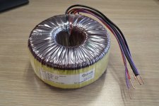
Did the wax actually penetrate the outer insulation foil?The best part has arrived! 🙂 These guys make incredibly good quality transformers. I haven't used better. Wax dipped as well (nice fuel for the fire).
Best regards!
No, I was calculating across the whole bridge.The information was in there. You didn't read/understand it.
Sigh. I was acknowledging this in my previous answer.
Did the wax actually penetrate the outer insulation foil?
Best regards!
I'm not sure. First of all, what are you referring to as the outer insulation foil?
I do want to find out what is actually dipped in wax, but I suspect each winding is. So I would guess it's the core, insulation, primary winding (dipped), insulation, secondary winding 1 (dipped), insulation, secondary winding 2 (dipped), insulation, outer insulation. It takes more than a week to make this transformer for me. 🙂
I do want to find out what is actually dipped in wax, but I suspect each winding is. So I would guess it's the core, insulation, primary winding (dipped), insulation, secondary winding 1 (dipped), insulation, secondary winding 2 (dipped), insulation, outer insulation. It takes more than a week to make this transformer for me. 🙂
Ok, this would make sense.
Best regards!
This is the part I enjoy when building an amplifier. Design current without output bias is about 10mA. Wire it up, plug it in, turn it on and the ammeter reads 9.8mA instantly. Not a shimmy from the transformer, not a hum or a buzz. So far, perfect.
Setup is also a breeze. Spent a few hours monitoring the bias. It settled at 65 mA, and stayed there. Next on my to do list is to set up the second amplifier.
I did also plug in a speaker, and it's a quiet amplifier, as expected. I will need to do some measurements with a shorted input. But so far, everything is exactly as designed.
Oh, and the transformer does make a buzz on turn-on. I just didn't really notice it at first.
I did also plug in a speaker, and it's a quiet amplifier, as expected. I will need to do some measurements with a shorted input. But so far, everything is exactly as designed.
Oh, and the transformer does make a buzz on turn-on. I just didn't really notice it at first.
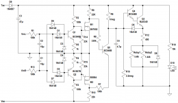
Amplifiers are set up and ready. I tested my DC protection and turn-on delay, and I'm not 100% happy with the circuit. It's not my design, but I'm using it for now. I have a better turn-on delay circuit, but I want DC protection too, so I'll need to design something.
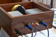
Now I need to build the enclosure.
Now I need to build the enclosure.
I designed a DC protection and turn-on delay circuit. The turn-on bit I've used in my other amplifiers, and I'm very happy with it. It shuts down nicely - you can turn off, and then turn on shortly after (haven't tested how long), say 1s later, and the turn-on circuit will delay the relays perfectly again. I believe it should work down to a few milliseconds, but I'm not sure (C4 discharges quickly through B-C of Q4). The 47uF filter capacitor lets the relays turn off in a few tens of milliseconds (more than fast enough), and this is convenient for the LED as well. 🙂
The DC protection filters the amplifier output to about 0.15Hz, and should have no false-triggers below 2.5 Hz. It will theoretically operate at +-2 Vdc up to the supply rails to protect expensive equipment from DC. It has a measure circuit for negative DC and one for positive DC, and then compares the output of each. It then inverts as necessary to get the correct voltage onto the relays. The nice thing is that it works seamlessly with the turn-on part for NO relays.
I haven't built this to tweak it yet, but I plan on doing so over the next few months. It is designed specifically for a 40-0-40 transformer supply (+-56-60 Vdc), and the transistors shown aren't what I'll use for the final thing (I want SMD transistors).
If you have comments about the circuit, you're welcome to criticize / suggest things. I'd actually very much appreciate it. I'm going to make everything surface mount, and also design a PCB for it. I'll post all the files here for anyone to use or modify as they wish.
Attachments
The amplifier looks great and works flawlessly. It sounds perfect, is dead quiet to the ear and it has lots and lots of headroom. I need to put the new DC protection and control circuit in. Without it, the wires are a little untidy, but it works perfectly now, so I'll do that in a few months' time. I just need to put the glass on top, feet at the bottom, and attach the fans.
I will measure the output soon as well, just to make sure.
I will measure the output soon as well, just to make sure.
Attachments

- Status
- Not open for further replies.
- Home
- Amplifiers
- Solid State
- New design 135W 8, 270W 4