I've closed the amp up and it looks great. I can still lift the top off if need be.
I had the amp on for a while at a reasonably high output for about an hour and a half. I felt the heatsinks and they must have been near about 50C. So I started doing the power/heat calculations again, and this is perfect. The amplifier heats up easier that any of my others, and it's because it's a significantly higher voltage than the others. Averaging 10 W output, the amplifier is dissipating around 50 W, so the sinks should get to about 45 - 50 C.
Maximum power dissipation for a 4 ohm load (nominal, so I can use average values for the heat calculation) will be in the region of 160 W, which will heat the sinks to s maximum of about 90 C. That's without fans. Each transistor case should then be at around 100 - 105 C. Using 100 C, the SOA derating factor is 0.4. The absolute maximum voltage and current into a 4 ohm resistive load is about 44 V (CE) and 3.6 A (Ic), or 0.72 A per transistor. On the derated DC SOA, this is very well within the SOA. If I double the current to take into account load variations, or a phase shift of a reactive load, it's still well inside the derated SOA.
I was a little worried because I thought I was very near the limits, but it turns out that this amplifier is well within limits. And then I have fans which come on at 60 C anyway.
Maximum power dissipation for a 4 ohm load (nominal, so I can use average values for the heat calculation) will be in the region of 160 W, which will heat the sinks to s maximum of about 90 C. That's without fans. Each transistor case should then be at around 100 - 105 C. Using 100 C, the SOA derating factor is 0.4.
Are you sure that your 100°C derating refers to case temperature? Usually derating is referred to junction temp. So, does your assumption still hold?
Best regards!
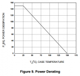
Yes, the 100degC case temperature gives a reduction from 150W to 60W and the permissible current at 60Vce also comes down to 1A
What is one device with a slightly poorer Rth c-s is mounted a a part of the heatsink that has a slightly higher interface temperature, then the Tc can easily be 5Cdegreees higher than the average for the group. That reduces it's maximum current to 0.9A when Vce=60Vce
And he still has not looked at what a reactive load does to the stresses applied to the output devices.
Yes, the 100degC case temperature gives a reduction from 150W to 60W and the permissible current at 60Vce also comes down to 1A
What is one device with a slightly poorer Rth c-s is mounted a a part of the heatsink that has a slightly higher interface temperature, then the Tc can easily be 5Cdegreees higher than the average for the group. That reduces it's maximum current to 0.9A when Vce=60Vce
And he still has not looked at what a reactive load does to the stresses applied to the output devices.
I have investigated the reactive load (bad reactive load), and I'm still within limits.
100C is an overestimate by a little in normal conditions and current per device at 60Vce is 0 mA (with a resistive load), since 60Vce is more than the supply.
I've calculated the worst possible condition for a 4 ohm load, and then doubled that current, and that is still within the SOA. And that's at 100C. And I have fans which come on at 60C.
At 50 Vce in a resistive load (4 ohms), Ic is 250 mA, and the derated SOA at 100C says that the maximum DC current allowed is 1.2 A.
The worst possible scenario is a 45 degree phase shift at 65V and 1.4A. I will admit that this is a little above the DC SOA, but it's just about below the 100ms curve. This means the 45 degree shift must happen at <10 Hz at full possible swing of the power supply without the power supply collapsing, and the frequency response already starts rolling off just before 10 Hz. And this is all at 100C, which is the maximum case temperature at room temperature for a 4 ohm nominal load, without fans.
Marc,I'm planing to build your amp. It looks good and simple.
Can you post your final schematic 'as built'?
What is the bias current per pair?
No need for base stoppers for parallel devices?
Any other advice or suggested improvements for builders?
Can you post your final schematic 'as built'?
What is the bias current per pair?
No need for base stoppers for parallel devices?
Any other advice or suggested improvements for builders?
Hi Minek. Good choice - it is indeed a good one! 🙂 I will post complete build instructions as soon as I can. The schematic I'll post will include component details, such as power ratings, etc. I will also include the power supply schematic, but you will need a DC protection and speaker on-delay circuit. This amplifier has no overload or short protection - I don't believe in using the unnecessary complexity. Just give me a few hours to get the details together.
Hi Minek. Good choice - it is indeed a good one! 🙂 I will post complete build instructions as soon as I can. The schematic I'll post will include component details, such as power ratings, etc. I will also include the power supply schematic, but you will need a DC protection and speaker on-delay circuit. This amplifier has no overload or short protection - I don't believe in using the unnecessary complexity. Just give me a few hours to get the details together.
Thanks Marc!!
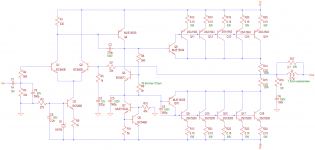
Hi Minek. I have attached the amplifier schematic. Give me a little time to also do the power supply. It's a busy day for me today, but I will post it within the next few hours.
If you can get a 150 V capacitor for C3, that will be even better. Please note the voltage and power ratings I have put in the schematic.
Q5 must be in thermal contact with Q8 or Q10. It is best to do this with a zip tie.
All resistors without a power rating noted must be 0.5 W metal film. Each of these generally won't dissipate more than 100 mW and higher tolerance resistors will be fine, but I suggest to use the 0.5 W metal film for better noise performance.
The 5 W and 10 W resistors are wire-wound. I know many on these forums use non-inductive composite resistors. It's up to you. I have no issues with the wire-wound resistors.
C8 is optional (it attempts to make D1 less noisy, which I don't think is a problem in the first place).
Q4, Q6, Q8, and Q10 must all be on small heatsinks (I used small TO-220 clip-on heat sinks). I also prefer to put them each on their own small heatsink.
I mounted all 10 output transistors on a 0.4 K/W heatsink using a Silpad for each one. But then I used a 60 Celsius thermal switch to turn on a fan blowing onto the heat sink. You could use a 0.4 K/W heatsink per 5 output transistors without a fan. It all depends on your enclosure.
If you can use 200 W or 250 W devices (MJE15003/MJE15004 for example), that would also be better, but I used 2SA1943 and 2SC5200, so I can't say for 100% certainty that the other output transistors will work (in terms of stability), but they should. I would highly recommend the higher power output transistors too - they aren't even that much more expensive.
R9 shows 5k as the value and states a 5k 10 turn trimmer. This means you must set it to maximum resistance before you turn on. You decrease the value until total amplifier quiescent current is about 100 mA. I set mine to 70 mA, and it's perfectly fine. It took me at least 1 hour of monitoring the output current to ensure that the bias point was perfect.
When you turn on initially, the total amplifier current should read 9 - 15 mA (ideally 14 mA, but it's not critical).
You can use Rod Elliott's loudspeaker protection and muting to interface the amplifier to the speakers. I'm using something similar as a temporary solution, and I have my own design, but it isn't tested yet.
Please take note that Q5 is a BC547 (use B or C version). I use this transistor (rather than a BC546) because it works well to set the bias point. I wouldn't use another transistor in its place.
I unfortunately can't give you a PCB layout at the moment. I used a single-sided PCB, but a double-sided one would be better and easier. My PCB layout needed a modification when it came time for building because I didn't give enough space for one or two components, and I didn't put Q5 and Q8 quite in the ideal position. I also didn't put the correct connections onto the board because I didn't quite know how I was going to connect the input, output, ground and power supply. I need to still work on the layout, and I won't be able to do this for a few weeks - I have projects for people which need to be finished, and I am going away for a while next week.
Then, I'm going to tell you to use Speakon connectors for your speaker outputs. It's not a suggestion, it's a command! 😀 They're absolutely fantastic! I don't sell schematics, but your payment can be that you use Speakons. 🙂
Attachments
Thanks Marc!
1) I see you got rid of the current mirror feeding LTP. What was the reason?
2) As for Q5 (bias sensor), MJE340, or even BD139 won't do?
They are easier to mount..
3) Rails are at 50V, right?
I'll go with the same output transistors as you, I only need 100W/8 Ohm
Don't worry about the PCB, I was going to design my own,
Hi. Yes, I got rid of the current mirror because the open loop gain it provided was massive and I just didn't feel good about the amplifier's stability. With just a resistor it still has plenty of gain, but it seems to have more stability. I built a 50 W version with the current mirror, and I always just felt uneasy about it. The noise is still very low.
You can use an MJE340. I stay away from BD139's because I've had issues with them in the past. I find the MJE340 works extremely well as a bias control transistor. I used the BC547 because it's a better small signal transistor. Honestly, mounting a TO-126 is easy, but coupling a TO-92 isn't much more effort. If you choose to use the MJE340, then just try to use a plastic insulated one.
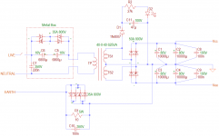
Rails are + and - 58 Vdc unloaded. 8 ohm power is 180 W. This amplifier can be used for less. Rather than a 40-0-40 transformer, use a 30-0-30. If you only plan on driving 8 ohms with 100 W, use a 250 VA transformer. Your rails for 100 W in 8 ohms will be about + and - 43 Vdc. There will be a change in the schematic (two actually):
1) Change R2 to an 18k
2) Change R10 to a 33k
Then there are some changes which you can optionally do, and I say why not?
1) You can change R11 to 100 ohms for less power in the VAS
2) You can use 2 pairs of output transistors rather than 5 if you only plan on driving 8 ohms to 100 W. If you want to drive 8 ohms to 100 W, but also want to connect 4 ohms at some point, use 3 pairs.
You could also use TIP35C and TIP36C for the +-43 Vdc supply - 3 pairs minimum. I know a lot of people don't like them, but I do; I find them extremely robust, and they sound great. They're also cheaper and easier to get.
Set total quiescent current Iq = [20(Number of output pairs) + 5] mA
In the power supply, you can use 4 x 4700uF rather than 10000uF for +-43 Vdc, and you can use 63 V capacitors for these rather than 80 V.
I have attached the power supply schematic.
Please just note that you should stay away from using wires from your PCB to the output transistors as much as possible. If you do need them, try to keep them as short as possible.
And please be careful with mains wiring.
If you have any questions, please ask any time. I hope this is a rewarding build for you. I am certainly VERY satisfied with this amplifier - it is the 7th amplifier I have made for myself, and definitely my best yet (I won't be building another one for myself). 🙂 Coincidentally, I may be building this exact amplifier in 100 W version for a friend (if he goes the stereo power amplifier route for his home stereo).
You can use an MJE340. I stay away from BD139's because I've had issues with them in the past. I find the MJE340 works extremely well as a bias control transistor. I used the BC547 because it's a better small signal transistor. Honestly, mounting a TO-126 is easy, but coupling a TO-92 isn't much more effort. If you choose to use the MJE340, then just try to use a plastic insulated one.
Rails are + and - 58 Vdc unloaded. 8 ohm power is 180 W. This amplifier can be used for less. Rather than a 40-0-40 transformer, use a 30-0-30. If you only plan on driving 8 ohms with 100 W, use a 250 VA transformer. Your rails for 100 W in 8 ohms will be about + and - 43 Vdc. There will be a change in the schematic (two actually):
1) Change R2 to an 18k
2) Change R10 to a 33k
Then there are some changes which you can optionally do, and I say why not?
1) You can change R11 to 100 ohms for less power in the VAS
2) You can use 2 pairs of output transistors rather than 5 if you only plan on driving 8 ohms to 100 W. If you want to drive 8 ohms to 100 W, but also want to connect 4 ohms at some point, use 3 pairs.
You could also use TIP35C and TIP36C for the +-43 Vdc supply - 3 pairs minimum. I know a lot of people don't like them, but I do; I find them extremely robust, and they sound great. They're also cheaper and easier to get.
Set total quiescent current Iq = [20(Number of output pairs) + 5] mA
In the power supply, you can use 4 x 4700uF rather than 10000uF for +-43 Vdc, and you can use 63 V capacitors for these rather than 80 V.
I have attached the power supply schematic.
Please just note that you should stay away from using wires from your PCB to the output transistors as much as possible. If you do need them, try to keep them as short as possible.
And please be careful with mains wiring.
If you have any questions, please ask any time. I hope this is a rewarding build for you. I am certainly VERY satisfied with this amplifier - it is the 7th amplifier I have made for myself, and definitely my best yet (I won't be building another one for myself). 🙂 Coincidentally, I may be building this exact amplifier in 100 W version for a friend (if he goes the stereo power amplifier route for his home stereo).
Attachments
- Status
- Not open for further replies.
- Home
- Amplifiers
- Solid State
- New design 135W 8, 270W 4