But a noob here, but what I've learned is that for safe driving of 4 ohm speakers, you need to calculate 2xPD at 2 ohm •1.41.
So a 333w/4ohm needs a PD of 939W. That's more then 5 150w devices.
And you need 25.75Amps at 56.4V... So check SOA again.
Also, that output arrangement? Been there, done that... Good luck!
Twin Bjt Sziklay output is tough.
So a 333w/4ohm needs a PD of 939W. That's more then 5 150w devices.
And you need 25.75Amps at 56.4V... So check SOA again.
Also, that output arrangement? Been there, done that... Good luck!
Twin Bjt Sziklay output is tough.
But a noob here, but what I've learned is that for safe driving of 4 ohm speakers, you need to calculate 2xPD at 2 ohm •1.41.
So a 333w/4ohm needs a PD of 939W. That's more then 5 150w devices.
And you need 25.75Amps at 56.4V... So check SOA again.
Also, that output arrangement? Been there, done that... Good luck!
Twin Bjt Sziklay output is tough.
With 12 years designing and building experience, I haven't experienced the need for that much overkill. The real problem appears to come in when the phase is shifted 45 degrees. Worst case is pure reactance, but this is impossible. Of course you're going to smoke your amp if you short the output with a capacitor. This is the equivalent of 90 degree phase shift.
At 330 W, and a 45 degree phase shift, the maximum theoretical total dissipation for 5 devices is 660 W. This is below the rating of those transistors. And it is an extremely unlikely event if you are listening to music. Impedance generally increases significantly at the points where the phase shift is around 45 degrees.
I've had a TIP35C/6C output (two pairs) in a 150 W driving a pair of KEF IQ9's for over 10 years. The guy who the amp was built for absolutely abused that amplifier. The only thing that blew was one of the IQ9s' crossovers. A few KV mains surge which blew transformers out the wall socket (and took down every single appliance in the house) was the only thing that could take that amp down.
And the twin Sziklai pair? I've got it down! I've been using it like this for years. My current amp is a 130W with one pair of 5200/1943 in this configuration, and it's 100% stable.
Now, this isn't the ideal design point, but also consider that the power supply regulation cannot sustain this sort of power. A well regulated and rated transformer may lose a mere 5% at a sustained sine wave output. The power is already going to drop to about 290 W if this is the case.
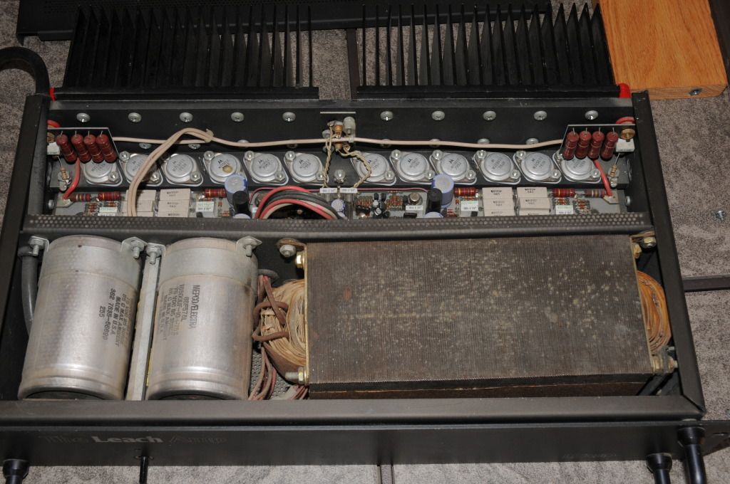
Also research the famous Leach amp. It uses two pairs of 250W transistors for 200W. That's more or less the same ratio of output power to device power rating as this 5 pair design. Additionally, some Leach amplifiers use 2 pairs of 200W rated devices...
The Leach LSR&D 101 seems to be bulletproof into a 2Ω load (28hz vented dual 15 monitors on music), three pair of 200W, 200°C outputs.
With 150°C plastic you will generally need 2X as many devices.
With 150°C plastic you will generally need 2X as many devices.
The Leach LSR&D 101 seems to be bulletproof into a 2Ω load (28hz vented dual 15 monitors on music), three pair of 200W, 200°C outputs.
With 150°C plastic you will generally need 2X as many devices.
Well, there you go. I'm using 5 for half the minimum nominal load, and using less supply.
Nice thing is that these better transistors are becoming more available now. It used to be fairly difficult to come by these. I see that I can get MJ15003 and MJ15004 now for a good cost. These would certainly be a far better option! (keep the 5 pairs)
The 5200/1943 have better Hfe linearity, but I hardly think this is any advantage over MJ15003/4.
The 5200/1943 have better Hfe linearity, but I hardly think this is any advantage over MJ15003/4.
An externally hosted image should be here but it was not working when we last tested it.
The Leach has a very good heatsink arrangement for the outputs and drivers, and finally failed after about 30 years of hard use.
Small electrolytics had to be replaced every 7~8 years.
Owner would occasionally drive it 10dB into clipping, engaging the fold-back current limiting (making a huge 'farting' sound).
This unit came with 3x MJ15011/12, the earlier 2x 15003/04 was not as good.
Last edited:
An externally hosted image should be here but it was not working when we last tested it.
This is EXACTLY how my current 130 W is laid out! 😀
2pairs of 250W devices comes to a total Pmax of 1000W...................Also research the famous Leach amp. It uses two pairs of 250W transistors for 200W. That's more or less the same ratio of output power to device power rating as this 5 pair design. Additionally, some Leach amplifiers use 2 pairs of 200W rated devices...
using good SOA devices allows the 5 factor to be used and that predicts a maximum output of 200W into a severe reactance load.
But the Leach Lo Tim is not rated as a 200W amplifier. He used a 40-0-40Vac transformer and the power rating comes out at ~150W
That is well within the 200W max predicted by the formula: Max Power ~ = total Pmax / 5 to 6 for BJTs (divide by 4 for mosFETs).
I used 3 pair of plastic packaged 230W devices for a total Pmax of 1380W and this gave a maximum power prediction of 276W. My Leach clone would drive a 6ohms reactive speaker load to ~ 250W reliably.
The 1943/5200 are not in that class. Compare the permitted 100ms Ic @ 60Vce to a 2n3773 or mjl0302 @ 60Vce, then compare @ 80Vce.
Last edited:
150W devices x 10 = 1500W Pmax. Divide by 5 = 300.
The Leach with 2 pairs of output was 200W in 8 ohm, but was perfectly capable of driving 4 ohms. And 40-0-40 is about 180W in 8 ohms.
The Leach with 2 pairs of output was 200W in 8 ohm, but was perfectly capable of driving 4 ohms. And 40-0-40 is about 180W in 8 ohms.
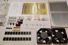
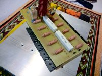
So it begins. My last components are due to arrive middle to late March. I have received some stuff, and I have gotten the PCB done, so I've started putting it together. I'll do it slowly but surely, and this is going to be a relaxed build. I've attached an image of everything I've already received, and what I've been able to build so far.
The only thing I'm thinking of changing is the thermal switch. I think a 65 degree one won't harm anyone, and then those fans may actually get some use.
The layout supports TO-3 devices, so future versions of this amplifier will probably use stronger devices.
The only thing I'm thinking of changing is the thermal switch. I think a 65 degree one won't harm anyone, and then those fans may actually get some use.
The layout supports TO-3 devices, so future versions of this amplifier will probably use stronger devices.
Attachments
I've got everything except the transformer, which is being made, and I'll get that next week. Very excited! I sadly also need to buy one more trim pot because a mix up caused only one to be ordered. But at least I can pop to a nearby shop to pick one up.
good decision to use a 65degree C temp switch rather than 95degreeC.
That will help reliability with the 1943/5200.
That will help reliability with the 1943/5200.
good decision to use a 65degree C temp switch rather than 95degreeC.
That will help reliability with the 1943/5200.
In addition, future versions will use TO-3 200-250W devices. They're available here now. It wasn't easy to get these in the past.
I'm just contemplating how to mount the transistors. I'm probably going to mount the transistors directly to the sink, but it might be easier in the future to do it like the attached for TO-3 devices. When mounting on a bracket like this, what are the implications?
Attachments
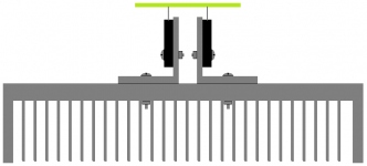
Use a 5mm thick L bracket and keep the outstanding leg holding the devices very short.
Use lots of bolts to attach the L to the sink.
If you mount the devices on the outside of the L you can get them much closer to the sink and that reduces Rth.
It is very hard to flatten the inside of an L. Quite simple on the outside.
Use lots of bolts to attach the L to the sink.
If you mount the devices on the outside of the L you can get them much closer to the sink and that reduces Rth.
It is very hard to flatten the inside of an L. Quite simple on the outside.
Thanks, I was thinking of 5mm. I would have to use the inside because of my layout with TO-264's, but with TO-3's it's easy to use whichever side. The problem is getting hold of 5mm aluminium. I'll research it for the future. For now, direct mounting will be perfectly fine.
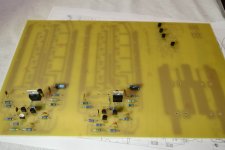
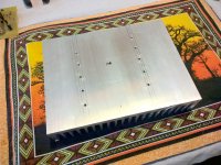
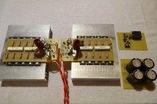
The build continues. I never enjoy mounting transistors. But it's done. For now. Drilling those holes and getting all the screws in is a PITA. Not to mention I had three screws strip - they were just bad screws.
I used Sil-pads, and after mounting, my continuity tester / diode tester shows a 1.6V drop from collector to sink for one of the amplifiers, but the resistance doesn't show (shows infinite). I think there is a minute connection from one of the transistors to the sink. I'm not going to worry about it.
There are a few things I need to revise on the PCB. When I originally designed it, I had the bias transistor next to one of the drivers, and then when I was planning the output inductor, I noticed a big gap and used that rather than the smaller gap I had left for it. The "big gap" was the space between the driver and the bias transistor, and I only realized this after printing them PCBs. Anyway, I've made do. There is one place where moving a capacitor will be nice, but otherwise, it's been a nice PCB to put together.
The transformer should arrive this week, then I'll have a test run.
Attachments
I would move the output coil and it's damping resistor off board.
Locating the inductor in the twisted pair that feeds the output terminals is a better place where it's field has less effect on the other circuits.
Locating the inductor in the twisted pair that feeds the output terminals is a better place where it's field has less effect on the other circuits.
I would move the output coil and it's damping resistor off board.
Locating the inductor in the twisted pair that feeds the output terminals is a better place where it's field has less effect on the other circuits.
I fully agree. I usually put the output crossover in the terminals. Here, however, the inductor is in the absolute ideal position - there is nothing below it on the PCB, nothing above it in the enclosure, and only a heatsink below the PCB. I have considered moving it, but I'll make a final decision when my enclosure layout is finalized as well.
"The Leach with 2 pairs of output was 200W in 8"
Three pair and 160W/8Ω.
±63V no load, 1KVA 90V CT no load.
Three pair and 160W/8Ω.
±63V no load, 1KVA 90V CT no load.

- Status
- Not open for further replies.
- Home
- Amplifiers
- Solid State
- New design 135W 8, 270W 4