Driving the HexFETs directly from VAS does not work well because of the HexFETs' high, non-linear input capacitance
Thanks, I've read about this.
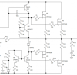
Would the attached work fine for 220 W 4 ohms? I would make the diode an LED, and I think the MJE340 makes a good bias control transistor.
Attachments

Thanks. I like it. If I try the MOSFETs, I'll investigate that layout, but looking at it initially, it's nice.
Are IRFP240s HEXFETs?
Are IRFP240s HEXFETs?
Thanks. I like it. If I try the MOSFETs, I'll investigate that layout, but looking at it initially, it's nice.
Are IRFP240s HEXFETs?
Absolutely.
All IRFPs like 240, 250, 260, as well as their complementary counterparts 9240, etc. are the same family, differing by power rating and some other parameters. They are all HexFETs.
What do you think of ALF16P16W and its N channel complement? Are they worth the cost? The datasheet looks fantastic.
Yes, they are very good, but they are laterals - they don't need the thermal feedback and can be driven directly from VAS. Bias voltage is lower. Sounding excellent if all the rest aspects of the design are good.
Pick one.
Laterals are designed for Audio, easy to bias, easy to drive, but are expensive.
Although considering total cost (transformer / chassis / heatsinks / big filter caps / PCB / cabinet / hardware) their contribution is minor.
Cheapskates like me, who make amps commercially where saving 1$ is a big deal, use Hexfets and similar which are powerful, cheap and robust but have important bias issues.
Do NOT add Leds to biasing circuits, for the very good reason that:
a) they do not track heatsink temperature, period.
A red Led will drop 1.9V across it at any temperature (ok, it might show a *minuscule* change, useless here)
b) they are never mounted to the heatsink anyway.
c) I have already made the same (expensive) mistake and had to recall a lot of amps for modding ... at my cost of course 🙁
b) you NEED that 2mV/centigrade variation , multiplied by the Vbe multiplier ratio , to safely track heatsink temperature.
Some do a little Math and state that it´s overcompensation.
Well, maybe ... if they were tracking actual die temperature, but since best they can do is track heatsink temperature, which is lower by definition, in the long run it ends up being somewhat compensated.
While a Led will track zilch. ("not at all", for non English readers).
Everything's right except some particular cases, like the one illustrated on my schematic.
The purpose of the LED in series with emitter is to reduce the spreader's sensitivity.
It's not on a heatsink, used as a stable, temperature independent voltage reference.
If it would not be there, the spreader would significantly overcompensate the bias.
The purpose of the LED in series with emitter is to reduce the spreader's sensitivity.
It's not on a heatsink, used as a stable, temperature independent voltage reference.
If it would not be there, the spreader would significantly overcompensate the bias.
Yes, the LED in the bias circuit is perfect where the MOSFET is driven with a BJT EF stage, near perfect tempco with vertical MOS.
It's such a mission finding decent transistors here in SA! I don't trust one place because I got fakes there before. Then there are a couple of places, but to find stock of what you want is mission impossible!
Bite the bullet and import your transistors. You can buy directly from most international online stores. The audio industry in SA is tiny, so there is not a good supply of well-supported, genuine parts locally. Even official distributors are living off scraps.
Happy tweaking!
Either the HEXFETs or those nice laterals fit the design, I just have to adapt it a little for whichever output I use. The only thing is that MOSFETs don't give as much swing as BJTs, but they are very rugged.
The last design I have on this thread aims to be very simple, but also very low noise and high quality. I also try to keep things a bit cheaper because I don't have the means to pay for all the components. To fulfil the requirement of keeping simple, the Darlingtons are great, they just can't be driven to high power. They're ideal for low power.
I must still do those square wave tests to confirm whether the Darlingtons are fine.
Now, each BDW costs about $0.50. A TIP35 costs $2 and a 5200 costs $2.30. Drivers cost about $1.10. The IRFP240s cost about $1.50 each. ALFs cost $8 each! Considering total cost for PCB, enclosure, heatsinks,etc. without the output stages is about $50, $32 for the ALFs is quite a lump. Everything else seems so cheap by comparison. The cheapest per watt seems to be the HEXFETs when power needs to reach around the 100W mark. I guess I'll see what compromises I need to make when the time comes.
Thanks for the help with those FETs!
Bite the bullet and import your transistors. You can buy directly from most international online stores. The audio industry in SA is tiny, so there is not a good supply of well-supported, genuine parts locally. Even official distributors are living off scraps.
Happy tweaking!
Heavy! When I got my 5200/1943s there weren't any at the time here. I basically had an opportunity to get from Digikey, but they were pricey! I guess you're right - I can find an output pair I like and stick to it if I import. Thanks!
Everything's right except some particular cases, like the one illustrated on my schematic.
The purpose of the LED in series with emitter is to reduce the spreader's sensitivity.
It's not on a heatsink, used as a stable, temperature independent voltage reference.
If it would not be there, the spreader would significantly overcompensate the bias.
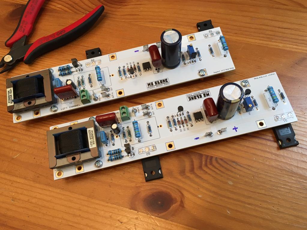
What do you think of the bias circuit in the Pass M2? I recently built this and it seems rock stable and even has a built in soft start (bias starts out low and slowly climbs up overn1 minute). There is no actual heatsink mounted temperature compensation and works well with IRFP240/9240. Can we adapt this to use on classic amp designs in this forum?
Based on patent but one on M2 is improved according to Mr Pass.
Here is implementation on M2 (the opto coupler and 1.25v references are not expensive). Seems the feedback is the current through the resistor network.
In actual practice - it's not that complicated - all those parts in the middle of the board between the two hexFETs. Sure, it's more than a BD139 and a pot and two resistors in cost - but it sure works well. There is no anxiety that the thing is going to meltdown.
Last edited:
I recently built this and it seems rock stable and even has a built in soft start (bias starts out low and slowly climbs up overn1 minute).
That's actually not a desirable trait for a bias circuit. The best bias circuit will be steady from start up to overheating. Ostripper's Slewmaster did this within 1mV across a pair of .22R emitter resistors. He even put his in he freezer for testing with no variation.
Hi Guys
mrcloc: Why do you use current mirrors as current sources rather than the 2-BJT feedback-controlled circuit? The latter is faster and you are using two BJTs anyway. I don't think the loss of 700mV in the feedback version is worth considering - that would mean you are clipping the amp.
Many designers view current sources/sinks as being "not part of the audio path" but they are mistaken. Those circuits are providing the 'push' or the 'pull' against a single-ended VAS or other stage, so their speed is just as important as the signal-driven half.
Also, if you use the mosfets in a CFP-style circuit with slight gain, then the gate voltage is no longer in series with the output voltage so the only loss is over R-ds.
Also: Mouser and Digikey are US vendors that ship worldwide and process orders in various currencies. Check them out. They carry many of the 2SA-2SC pairs and similar Fairchild FSA-FSC parts. They are reputable and work hard to deal only with legitimate suppliers.
Optical bias: Seems pointless. The optocoupler is intended to provide voltage isolation over hazardous barriers, such as monitoring something tied to the mains. What is the point in a bias spreader? It seems like something clever to do, but "clever" is often a mistake. Optocouplers have a small but always-present transmission delay between input and output.
Have fun
Last edited:
ptical bias: Seems pointless. The optocoupler is intended to provide voltage isolation over hazardous barriers, such as monitoring something tied to the mains. What is the point in a bias spreader? It seems like something clever to do, but "clever" is often a mistake. Optocouplers have a small but always-present transmission delay between input and output.
The point here is that the opto-coupler is not used for voltage isolation but as a means to de-couple the current being sensed from the current controlling the bias. It uses the current across the drain resistors to power the LED to optically bias the photo-transistor as the bias spreader. Note that it allows feedback via current sensing rather than actual temperature sensing. The time delay of a optocoupler is probably nanoseconds, but at any rate, here is not important as it is not in audio path with the big 3.3mF cap acting as a large time constant filter. I think the cap could be reduced to typical levels like 1uF to give a speedier response but what I saw in using this setup with the M2 is that the bias current was very stable.
Member
Joined 2009
Paid Member
or common sourceAlso, if you use the mosfets in a CFP-style circuit with slight gain, then the gate voltage is no longer in series with the output voltage so the only loss is over R-ds.
or single ended emitter follower.Driving the HexFETs directly from VAS does not work well because of the HexFETs' high, non-linear input capacitance (no problem with laterals, but a problem with HexFETs). Solution - push-pull EF stage between the VAS and the HexFETs.
for examples of both, see here: http://www.diyaudio.com/forums/solid-state/239418-tgm7-amplifier-based-greg-ball-ska.html
Last edited:
Optical bias: Seems pointless. The optocoupler is intended to provide voltage isolation over hazardous barriers, such as monitoring something tied to the mains. What is the point in a bias spreader? It seems like something clever to do, but "clever" is often a mistake. Optocouplers have a small but always-present transmission delay between input and output.
Hi Struth,
Do you mean, the light has to cross that space between the transmitter and the receiver? 🙄 Just kidding 😉 I know what you mean, but just imagine how many orders slower the thermal feedback is.
The point is that such a biasing system is monitoring the current directly, not the secondary thermal effects, caused by that current. This kind of principle is often used particularly in class A designs, as they operate in much hotter region of the temperature swing (which is not that linear - the threshold gets narower in the region of high temperatures). Musical Fidelity is using direct current monitoring in its class A amplifiers for years - no current couplers, but DC feedback is arranged appropriately.
For class AB designs the normal bias spreader is a simple and reliable solution, as far as it is arranged and tuned the right way - spreader's tempco is key, plus its phisical arrangement is important.
Cheers,
Valery
- Status
- Not open for further replies.
- Home
- Amplifiers
- Solid State
- New design 135W 8, 270W 4