
Those adapters from Hoppe's Brain looks pretty cool
 .
.

https://hoppesbrain.com/product/to3-to-to3p-adapters/ web.archive
https://hoppesbrain.com/product/mt-200-to-3p-adapters/ web.archive
Scrolling down those two web links shows a pretty detailed description with pictures how to solder a transistor case onto the copper adapter, a quick skim through and the take away seems to be,

-TO3 Mechanical Interchangeability.jpg")
ps. click to enlarge images.
Note to self: Unicode input ° Degree symbol, Ctrl + Shift + u (Enter) 00B0
https://hoppesbrain.com/product/to3-to-to3p-adapters/ web.archive
https://hoppesbrain.com/product/mt-200-to-3p-adapters/ web.archive
Scrolling down those two web links shows a pretty detailed description with pictures how to solder a transistor case onto the copper adapter, a quick skim through and the take away seems to be,
- use Eutectic solder paste which melts at 183° C
- use alligator clips to clamp the transistor onto the adapter
- use hot air gun set to 350° C and start with heating up the transistor case for 10 seconds, then continue heating from underneath, ie the adapter side.
ps. click to enlarge images.
Note to self: Unicode input ° Degree symbol, Ctrl + Shift + u (Enter) 00B0
Last edited:
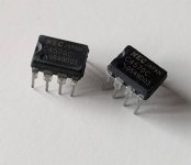
They look reasonable maybe.
Where did you get them, and were they "new manufacture"?
I have some original ones, the "NEC" print is smaller and finer, the rest more coarse. Enough so I am suspicious and where they came from may tip the balance.
Where did you get them, and were they "new manufacture"?
I have some original ones, the "NEC" print is smaller and finer, the rest more coarse. Enough so I am suspicious and where they came from may tip the balance.
Not sure what the point about these is. You could fit the non-TO3 transistors in the same way to the heatsink without the Brain plate in between (outer pins straight to their holes, middle pin bent up to the screw). Also, Brain seems to use anodized screws for electrical contact of the middle pin, which does not seem like a great idea to me.Those adapters from Hoppe's Brain looks pretty cool
I feel you might be underestimating the impact of a heat spreader. The 2sa1294 is rated for 130w, but that same package, welded on to an MT200 back plate is called the 2sa1295. Same wafer, just larger mating plate and is rated for 200w.Not sure what the point about these is. You could fit the non-TO3 transistors in the same way to the heatsink without the Brain plate in between (outer pins straight to their holes, middle pin bent up to the screw). Also, Brain seems to use anodized screws for electrical contact of the middle pin, which does not seem like a great idea to me.
This adapter is not necessary as you suggest, rather another tool for thermally managing total dissipation. Given the kind of heatsinking available.
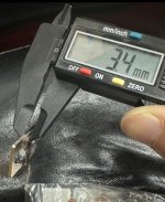
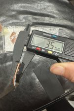
The backplates for MT200 are thicker than the adapters are. So that puts you somewhere in between. Better, but not equal.
Not sure what the point about these is. You could fit the non-TO3 transistors in the same way to the heatsink without the Brain plate in between (outer pins straight to their holes, middle pin bent up to the screw). Also, Brain seems to use anodized screws for electrical contact of the middle pin, which does not seem like a great idea to me.
MT-200's don't use the heat-spreader for electrical connection to the collector, like a TO-3 does.
However, you can actually use black-oxide coated steel hardware for electrical connections, it comes industry recommended, and they work fine on TO-3's. (This was a surprise to me too but I did some research.) Black-Oxide coating is Fe3O4, (AKA magnetite) not Fe3O3 (AKA rust) and has much better electrical conductivity. Additionally, the coating is extremely thin, around 0.5uM, and cuts through on tightening the fastener.
Brass screws conduct better than steel, but a few mm of M3 steel bolt is going to contribute very little to the circuit.
ETP Copper as used in electronics has a thermal conductivity of 390 W/mK, and 6063 and 6060 aluminum used in heatsinks is 201 W/mK and 166 W/mK, respectively. This is why MT-200's have so much more copper mass than TO-3P's. Heat gets wicked away from the hot-spot under the transistor die quicker, when there is more copper, not aluminum. The heat-spreader increases the surface area of the contact patch where the copper meets aluminum, and reduces the delta temperature difference between those surfaces, so the heat is transferrered more efficiently to the heatsink.
Good idea! Cheerscheck the quiecent current according to the data sheet
Sometimes something surprisingly simple can elicit a signature of a genuine versus a fake part. Such as driving the op-amp with a square wave into clipping and watching the slewing and clipping behavior (with a scope). But you need a reference genuine part to compare to. If you have a genuine part, a scope and a generator you might try this. Combine that with quiescent current and input bias current and you can weed out many fake op-amps. Before I bought a "real" scope I was able to do this with an eBay DSO138 and uncovered that most of my eBay and AliExpress audio op-amps were fakes.
Once I needed to buy some TL07x and got dozens of fakes from everywhere until find a store selling TL-07x from UTC Unisonic.Sometimes something surprisingly simple can elicit a signature of a genuine versus a fake part. Such as driving the op-amp with a square wave into clipping and watching the slewing and clipping behavior (with a scope). But you need a reference genuine part to compare to. If you have a genuine part, a scope and a generator you might try this. Combine that with quiescent current and input bias current and you can weed out many fake op-amps. Before I bought a "real" scope I was able to do this with an eBay DSO138 and uncovered that most of my eBay and AliExpress audio op-amps were fakes.
These ones from UTC worked fine for my needs and passed my tests.
I make the tests that matters for me:
-Quiescent current
-Sinewave driving minimum impedance (e.g 680ohms / 15V - 22mA peak) to observe if the opamp delivers the maximum current without distortion. All of the fakes had crossover distortion when loaded.
-Slew rate: drive minimum load with square wave and check the time it takes to swing from -12V to +12V, for example and compare to datasheet.
All the fakes had bad slew rates (10 times slower)
-Input impedance - check and compare to datasheet
-Noise: build high gain amp and measure the S/N ratio (I used RMS scope measurement) - compare with datasheet.
Similar to BJT power transistors (lot of complain of fake popular C5200/A1943 in my country):
For current and power tests I run for an hour at least.
-Hfe (using some IC points)
-Maximum VCE
-Maximum IC current: test at Tj=130C
-Power: choose V and I along the curve that producs maximum power allowed for Tj=130C
Absolute maximum power is difficult to test since you would need to keep Tc=25C.
-SOA Second Breakdown: choose some points of V and I along the second breakdown region curve at Tj=130C
-Build a simple amp topology (e.g. common emitter) to get a certain gain and check if the FT (MHz) is really around what is expected
Does anyone else make other additional tests?
- Home
- Design & Build
- Parts
- My Transistors, original or copy?