Popchops, the signal input cable i used for the Q-Watt was from Farnell UK.
Code 1891100 - VAN DAMME 268011C Multicore Screened Cable, Black, 24 AWG, 0.22 mm²
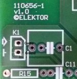
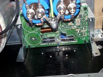
As Delange correctly said the screen connects to Ground on K1 connection (pin 2) and if there might be any 'hum' then the connection of the screen to Ground will do away with this.
Code 1891100 - VAN DAMME 268011C Multicore Screened Cable, Black, 24 AWG, 0.22 mm²
As Delange correctly said the screen connects to Ground on K1 connection (pin 2) and if there might be any 'hum' then the connection of the screen to Ground will do away with this.
Last edited:
And a nice Ambilight TV as well, you have it made delange
The ambiant light is not from the TV set.
I mounted LED spots upright in the furniture. There are two more lights but these are not in the picture. Of course, all of this is copyrighted delange 🙂
You are correct: I made that 😀
3) there is actually a third change: I removed the volume pot and replaced it with a 0 dB / -20 dB switch. I use a pi-pad attenuator to get the -20 dB attentuation. I only implemented the volume pot to pre-set it to certain level. This is easier accomplished with an attenuator. The pi-pad is soldered directly to the switch. I should have taken a detailed picture if that but I forgot 🙂
Delange might you kindly give a bit more info about this, when its possible.
It looks like another possibility to use.🙂
Delange might you kindly give a bit more info about this, when its possible.
It looks like another possibility to use.🙂
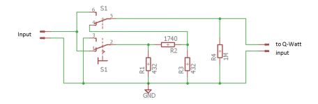
I used a DPDT switch to select either the input signal straight to the Q-Watt input or through a pi-pad attenuator. The attenuation is set to -20 dB and it is normalized to about 350 ohms. I have used this attenuator in my system before and it works very well with the Q-Watt as well.
I have attached the schematic in case you're interested.
Attachments
Superb Delange!
Interesting to see the values chosen.
It's normalized to about 350 ohms (impedance my pre-amp sees). The impedance should be low (but not too low). The values also set an attenuation of 20 dB. The values chosen fit that criteria.
What values would you have chooses?
Why is the input impedance set to 360ohms at switch position shown but set to 1000000ohms when in the other position?
Why does your Source need to see a load impedance of 350ohms?
Why does your Source need to see a load impedance of 350ohms?
about 350 ohms (impedance my pre-amp sees).
Last edited:
I also think that a Pi attenuator with equal input and output impedances doesn't provide significant benefit over a simple voltage divider in small signal AF applications. It has to be considered in loudspeaker services, though.
Best regards!
Best regards!
Maybe those in doubt would like to read some of interesting posts such as: -
https://www.allaboutcircuits.com/tools/pi-attenuator-calculator/
https://www.allaboutcircuits.com/tools/pi-attenuator-calculator/
Yes, impedance matching is essential in almost any RF application, but not necessary in small signal AF, where we don't need mximum power transfer. On top of that be careful with your chosen impedance value, as 350 ohms might present a severe load to some preamplifiers, thus unnecessarily causing distortions.
Best regards!
Best regards!
I also think that a Pi attenuator with equal input and output impedances doesn't provide significant benefit over a simple voltage divider in small signal AF applications. It has to be considered in loudspeaker services, though.
Best regards!
An advantage of the pi pad in audio is that you can reverse it (input - output). Of course, the one I used in the Q-Watt is fixed and cannot be reversed. But if you built one into a cable then you could reverse it.
The difference between a voltage divider and a pi pad is only 1 resister. A resistor is very cheap, so why not go for a pi-pad?
On top of that be careful with your chosen impedance value, as 350 ohms might present a severe load to some preamplifiers, thus unnecessarily causing distortions.
Best regards!
I initially built this to be used with my Audiolab M-DAC. It has an output impedance of less than 1 ohms. This is a very good design and devices such as these will have no issues with the chosen values.
I also have it running for several months on my Cambridge Audio pre-amp. Although I couldn't find any info on the output impedance of the CA but it works very well too.
Last edited:
The Sommer cable used by delange has two conductors and a foil shield. Three conductors? This is what confused me. Does the shield get connected to chassis? And the inner cores must be signal and signal gnd?
And... is the sommer cable twisted? Thx. Pops.
And... is the sommer cable twisted? Thx. Pops.
Last edited:
The Sommer cable used by delange has two conductors and a foil shield. Three conductors? This is what confused me. Does the shield get connected to chassis? And the inner cores must be signal and signal gnd?
And... is the sommer cable twisted? Thx. Pops.
The cable I used is a symmetric audio cable. It is intended to carry +, - and signal ground signals. Hence the three wires.
The Q-Watt is asymmetric ( 2 wires). So I connect the shielding to signal ground ( on one side of the cable). I use the green wire for signal ground. The white wire carries the audio signal.
Since you have the coax audio cable, you connect the signal ground to the shielding and the audio signal to the middle wire. That will work just fine.
Last edited:
The Sommer cable used by delange has two conductors and a foil shield. Three conductors? This is what confused me. Does the shield get connected to chassis? And the inner cores must be signal and signal gnd?
And... is the sommer cable twisted? Thx. Pops.
A screened twisted pair uses the two cores for the signal - Signal Hot/Flow and Signal Cold/ReturnThe cable I used is a symmetric audio cable. It is intended to carry +, - and signal ground signals. Hence the three wires.
The Q-Watt is asymmetric ( 2 wires). So I connect the shielding to signal ground ( on one side of the cable). I use the green wire for signal ground. The white wire carries the audio signal.
Since you have the coax audio cable, you connect the signal ground to the shielding and the audio signal to the middle wire. That will work just fine.
The screen/shield is connected to Chassis at both ends. The screen carries interference. This interference must not be transferred into the audio circuits.
The two internal cores must be twisted for the screen to be effective. Some screened 2core cable is not twisted.
If the screen is not circular, then the screening is not as effective and this can be particularly bad for the untwisted pair, where the screen can be decidedly oval if the fillers are not adequate.
A twisted star quad is slightly better if made accurately, than the twisted pair at keeping the centroid of the Flow and Return in the middle of the circular screen. This makes the interference attenuation a bit better.
Last edited:
Popchops, as i mentioned before the signal input cable i used for the Q-Watt was from Farnell, Code 1891100 - VAN DAMME 268011C Multicore Screened Cable, Black, 24 AWG, 0.22 mm², £1.51 per metre.
No hum, no feedback, no nothing, no interference, it work 101% tested!
Or something similar from Maplin is Code: N86DL.
As a fellow constructor you'll see in the image the connections, wording in black text.
No hum, no feedback, no nothing, no interference, it work 101% tested!
Or something similar from Maplin is Code: N86DL.
As a fellow constructor you'll see in the image the connections, wording in black text.
Attachments
Last edited:
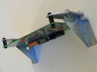
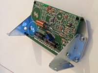
I found a simple bracket design for the Q-Watt that uses steel right-angled corner brackets from Ebay and 25mm aluminium strip. Allows the PCB to be mounted on the heatsink for strain relief on the semiconductor pins, and also for testing separate from the rest of the case.
Works in a 3U case with the highest/largest chips mounted on the centreline of the heatsink.
Pops.
Works in a 3U case with the highest/largest chips mounted on the centreline of the heatsink.
Pops.
Attachments
Last edited:
No hum, no feedback, no nothing, no interference, it work 101% tested!
As a fellow constructor you'll see in the image the connections.
Thanks Calpe. Did you all use the small black 0.1" connectors supplied by Elector for audio IN. They look quite fragile to me. But then I have been known to overengineer everything...
popchops, in my case i used the below items from Farnell: -
(needed them also for the Elektor Preamplifier 2012 https://www.elektormagazine.com/labs/preamplifier-2012-1-introduction-and-line-intonevolume-board-110650): -
Farnell: -
Code 9729038, £1.81 for strip of 5 pieces.
Code 9728856, £2.64 for 1 strip.
I also used Maplin Insulated Spade Terminal Female (several colours available) e.g. JH88V
Although you crimp the cable in the spade terminals, i added a small amount of solder for security.
Last edited:
These 0.1" pin pitch SIL (single in line) pins are available in dual in line (DIL) and both of those are available in straight and right angle.
There are SIL and DIL plugs to match.
Mechanical grip onto a few pins is not strong.
Even if you have only three pins, I suggest you try to make space on the PCB for a DIL version and make it longer. A DIL 5+5pins plug locks onto the 10 pins far better than onto 3pins. You can even double up the pins for each siganl contact to reduce contact resistance.
- Home
- Amplifiers
- Chip Amps
- My Q-Watt project