Thanks all. I do have a 75W 47R resistor but itwould still be destroyed in case of relay failure and would probably absorb a great deal more energy first. Separate resistors cool faster.
I will have a think about a plastic tub to put over the soft start.
Pops.
The reason I mentioned the 50 watt resistor was purely for mechanical reasons not for power dissipation. Those encased resistors are easier to mount.
All connections that carry mains are getting isolated in my builds (for example by applying shrink tube).
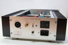
Finished my second channel; in a mini disipante enclosure.
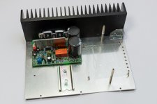
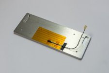
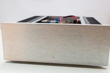
Since there isn’t much room to spare inside, I had to modify the enclosure a bit. I used a 2 mm thick aluminum bottom plate instead of the default bottom plate that came with the enclosure. The bottom plate is fixed to the heatsinks from the bottom side. This way I didn’t needed the metal brackets and that freed up some space I needed to fit the amplifier PCB close to the heatsink. The mini disipante is a nice enclosure but some of the construction is not well thought through. For example, it is not easy to mount the front and back panels when the enclosure is well filled. The back panel I used is also screwed into the heatsinks.
I made some changes to the setup as well. I now have fitted the 12 volts trigger relay inside the enclosure. I’m using a trigger signal from my pre-amp to switch the power. I use a second relay to switch the opto-coupler and the power LED. The AUX supplies of the SMPS’s have fairly large buffer caps; the relay switches of the opto-coupler immediately as soon as power is removed. With this setup I don’t need the “larger” resistors to drain the buffer caps.
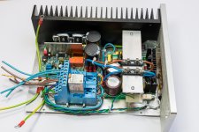
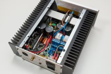
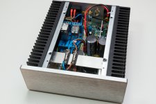
I’m in the process of converting my first channel to a mini disipante enclosure as well. I’m quite happy with the result. I attached some pictures of the various steps during the construction.
Since there isn’t much room to spare inside, I had to modify the enclosure a bit. I used a 2 mm thick aluminum bottom plate instead of the default bottom plate that came with the enclosure. The bottom plate is fixed to the heatsinks from the bottom side. This way I didn’t needed the metal brackets and that freed up some space I needed to fit the amplifier PCB close to the heatsink. The mini disipante is a nice enclosure but some of the construction is not well thought through. For example, it is not easy to mount the front and back panels when the enclosure is well filled. The back panel I used is also screwed into the heatsinks.
I made some changes to the setup as well. I now have fitted the 12 volts trigger relay inside the enclosure. I’m using a trigger signal from my pre-amp to switch the power. I use a second relay to switch the opto-coupler and the power LED. The AUX supplies of the SMPS’s have fairly large buffer caps; the relay switches of the opto-coupler immediately as soon as power is removed. With this setup I don’t need the “larger” resistors to drain the buffer caps.
I’m in the process of converting my first channel to a mini disipante enclosure as well. I’m quite happy with the result. I attached some pictures of the various steps during the construction.
Attachments
Very nice Delange. Looks like a work of art.
Pops.
Thanks Pops.
Hope it helps / inspires others.
Hi delange.
What type of wire did you use there to connect to the RCA audio input?
I don't know whether to use two stranded wires, twisted, or else coaxial cable with a solid core and outer shield.
What say you folks?
Pops.
What type of wire did you use there to connect to the RCA audio input?
I don't know whether to use two stranded wires, twisted, or else coaxial cable with a solid core and outer shield.
What say you folks?
Pops.
Delange, fantastic piece of work, especially from a fellow constructor too.
It would be interesting to read a detailed description on the design and circuitry of: -
"I made some changes to the setup as well. I now have fitted the 12 volts trigger relay inside the enclosure. I’m using a trigger signal from my pre-amp to switch the power. I use a second relay to switch the opto-coupler and the power LED. The AUX supplies of the SMPS’s have fairly large buffer caps; the relay switches of the opto-coupler immediately as soon as power is removed. With this setup I don’t need the “larger” resistors to drain the buffer caps."
Popchops, i used audio single core, screened cable, got it from Farnell, code no. 1891100, but Maplin have something similar too http://www.maplin.co.uk/search?text=audio+screened+cable&x=0&y=0
Last edited:
Hi delange.
What type of wire did you use there to connect to the RCA audio input?
I don't know whether to use two stranded wires, twisted, or else coaxial cable with a solid core and outer shield.
What say you folks?
Pops.
I'm using Sommer ISOPOD SO-F22 cable. Sommer calls this installation cable I believe.
You could use standard twisted cable if there isn't a source nearby who injects hum into your cables. For example: if your input cables are near a transformer you better use cable with shielding. In my case, I don't have such a source nearby but I used shielded cable anyway. Just for peace of mind and I have the above mentioned cable available. I bought a 100 meter reel a few years back.
Delange, fantastic piece of work, especially from a fellow constructor too.
It would be interesting to read a detailed description on the design and circuitry of: -
"I made some changes to the setup as well. I now have fitted the 12 volts trigger relay inside the enclosure. I’m using a trigger signal from my pre-amp to switch the power. I use a second relay to switch the opto-coupler and the power LED. The AUX supplies of the SMPS’s have fairly large buffer caps; the relay switches of the opto-coupler immediately as soon as power is removed. With this setup I don’t need the “larger” resistors to drain the buffer caps."
Thanks for the kind words Calpe.
I like the creative process involved in such builds.
Well it is actually simpler than it sounds:
1) The 12 volts trigger relay: in my previous enclosure I didn't have the room to include it. The relay is activated by a 12 volts trigger signal coming from my pre-amp. The relay switches the mains to my SMPS, just like a mains power switch does. In other words, with the trigger signal my Q-Watt's switch on when my pre-amp switches on.
<slightly off topic>
I'm now starting a small project that takes the 12 volts trigger from my pre-amp and uses that to create 4 different 12 trigger outputs. These 4 outputs will be active delayed: when the pre-amp switches on, the 4 trigger outputs of my new project will become active one after the other with a slight delay between them. I do this to power on different components in my hifi system at a different interval.
</slightly off topic>
2) The second modification is about providing the required input to the opto-coupler. I my previous build I used two resistors and a fet to switch the power supply to the opto-coupler fast. Fast meaning as soon as the amp is switched off, the supply to the opto-coupler should be cut as soon as possible. I now have a relay who does that instead of the resistors and the fet? Why did I do that: because I could. The fet works just as well and is smaller than the solution with the relay. I retrospect, I would use the fet again because my mini disipante enclosure is packed...
3) there is actually a third change: I removed the volume pot and replaced it with a 0 dB / -20 dB switch. I use a pi-pad attenuator to get the -20 dB attentuation. I only implemented the volume pot to pre-set it to certain level. This is easier accomplished with an attenuator. The pi-pad is soldered directly to the switch. I should have taken a detailed picture if that but I forgot 🙂
Last edited:
A very nice amplifier, looks proffesional Mr.delange, bic difference when compare with my "old Marantz"
Peterphuket, your's too was a great build. It's great to see all ideas the Q-Watt constructors have.
Thank you Calpe, very kind of you.
I read all the comments, and it is very nice to see how everybody apply there own idees.
But for this reason this a very good project.
As I wrote before, I built "the Preamp" from Elektor, and still full satisfied, but already 31 years ago!
I read all the comments, and it is very nice to see how everybody apply there own idees.
But for this reason this a very good project.
As I wrote before, I built "the Preamp" from Elektor, and still full satisfied, but already 31 years ago!
A very nice amplifier, looks proffesional Mr.delange, bic difference when compare with my "old Marantz"
Thanks Peterphuket !
I like your project as well. It's a great idea to put new life in an amplifier who died.
Are you using the Q-Watt's in your main system?
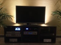
I finished converting my first channel into the mini disipante enclosure. Attached is a crappy picture of the two mono blocks in my system.
Attachments
I got 15 metres of this 'audio coax' from Maplins a few weeks ago, for £0.09 per metre!?You could use standard twisted cable if there isn't a source nearby who injects hum into your cables. For example: if your input cables are near a transformer you better use cable with shielding. In my case, I don't have such a source nearby but I used shielded cable anyway. Just for peace of mind and I have the above mentioned cable available. I bought a 100 meter reel a few years back.
Profigold Audio Single Sheathed Single Core | Maplin
Pops.
Hi delange. Thanks. Did you ground the braided shield, separate from the signal ground? Will this give greater immunity vs. coax cable?I'm using Sommer ISOPOD SO-F22 cable. Sommer calls this installation cable I believe.
I understand that if I use coax the braided shield will also serve as signal ground.
Pops.
Hi delange. Thanks. Did you ground the braided shield, separate from the signal ground? Will this give greater immunity vs. coax cable?
I understand that if I use coax the braided shield will also serve as signal ground.
Pops.
The shielding is connected to signal ground, not to PE (if that's what you mean by grounding). The signal ground on the shielding will prevent external "hum" to enter the signal path though the cable.
The coax cable you have will work as well. Just connect the shield to signal ground.
Thanks Peterphuket !
I like your project as well. It's a great idea to put new life in an amplifier who died.
Are you using the Q-Watt's in your main system?
I finished converting my first channel into the mini disipante enclosure. Attached is a crappy picture of the two mono blocks in my system.
Yes at the moment i using it in the main system.
I set aside the other amp, I have used for many years from ALBS from Germany, 2 separate blocks with 200W mosfets each.
But I have here another oldy, the Marantz SM-6, it had a burned out voltage amplifier, I made a new print with all the parts, but still waiting for some capacitors.
When it is finished, I like to compare it with the Q-Watt.
Anyway later, when all finished I can make choice for 3 amps🙂
But you can listen only one at a time😱
If you use a coaxial cable as your signal connection, then this two wire connection uses BOTH wires to complete the signal circuit.Hi delange. Thanks. Did you ground the braided shield, separate from the signal ground? Will this give greater immunity vs. coax cable?
I understand that if I use coax the braided shield will also serve as signal ground.
Pops.
The screen is the signal just as much as the core is the signal. Break either and you lose the connection.
Do not think of the coaxial as a one wire connection system with a ground.
It is a TWO wire connection.
this is what a coaxial is not good at. It is far better at attenuating higher frequency interference....................The signal ground on the shielding will prevent external "hum" to enter the signal path though the cable. ................
A screened twisted pair is good at attenuating low frequency interference because the twisting helps cancel the interference effect. Screened star quad is even better. That's why star quad is used as microphone cable.
- Home
- Amplifiers
- Chip Amps
- My Q-Watt project