It's down to personal preference.
I've used what i've stated and am more than happy with it. 🙂
All mounted without any problems, nor contact resistance. 😀
My life and my Q-Watt project that i constructed were in my hands when i begun this project, I'm still alive and my Q-Watt is working and sounds fantastic! 😀
I've used what i've stated and am more than happy with it. 🙂
All mounted without any problems, nor contact resistance. 😀
My life and my Q-Watt project that i constructed were in my hands when i begun this project, I'm still alive and my Q-Watt is working and sounds fantastic! 😀
Last edited:
Thanks Andrew. That's my concern... the PCB design allows two such pins to be soldered on but I know they are fragile. I don't want to change the PCB but I could use a different connector...Mechanical grip onto a few pins is not strong.
Even if you have only three pins, I suggest you try to make space on the PCB for a DIL version and make it longer.
popchops, as you know (having the pcb) it's a double sided print & with what i have used it's actually very sturdy.
I'm very happy with what i used and it's very solid 🙂
I'm very happy with what i used and it's very solid 🙂
Good point... maybe I can solder both sides...? Whenever I tried soldering with these 0.1" connectors in the past the black plastic links just tun to goo... I really hate them. Is it a bad idea to skip the connector and solder the stranded input wires direct through the PCB? At least that wont drip plastic or fatigue off...
Last edited:
As you have been soldering the components (pcb upside down) you'll have noticed that some of the solder passes through the 'holes' into what is the upper side of the pcb, so by rights just add add a tiny 'drop' more of solder onto these points.
If after you have soldered you don't 'see' enough solder on the top of the pcb, just add a tiny drop more on the top side.
My life and my Q-Watt project that i constructed were in my hands when i begun this project, I'm still alive and my Q-Watt is working and sounds fantastic!
If after you have soldered you don't 'see' enough solder on the top of the pcb, just add a tiny drop more on the top side.
My life and my Q-Watt project that i constructed were in my hands when i begun this project, I'm still alive and my Q-Watt is working and sounds fantastic!
Last edited:
Whenever I tried soldering with these 0.1" connectors in the past the black plastic links just tun to goo...
Is it a bad idea to skip the connector and solder the stranded input wires direct through the PCB?
Popchops, if the black platic links turn to goo, you're leaving the soldering iron on the solder joint for too long.
You should tin the Inner cable and shield before soldering to the black pins, but also tin the pins too.
You can then wrap the inner cable around the pin and solder together.
The same would apply to the shield cable, but make sure that all the strands are twisted tightly together. To wrap the shield cable around the pin could be tricky and probably too thick, in which case just apply a 'blob' of solder to the pin and introduce the cable towards the pin and solder together.
To insert the cables through the pcb holes and solder sounds ok, but, it'll be difficult to pass the shield cable through the hole.
Thanks Calpe. Did you all use the small black 0.1" connectors supplied by Elector for audio IN. They look quite fragile to me. But then I have been known to overengineer everything...
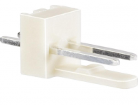
They are indeed quite fragile. I used a different connector (see attached picture). That connector works very well and it gives me peace of mind 🙂
Attachments
Delange looks a sturdy connector.
Perhaps it's type name code no. might help popchops
There are many variations from many manufactures of these type of connectors. I bought these at Conrad: BKL Electronic 072639 Straight Terminal Strip Number of pins: 3 Nominal current: 2 A from Conrad Electronic UK
The ones I used have three pins (because I had them available). But it's easy to cut or bend one pin. They work wonderful.
popchops, the connector delange has used look very solid.
Have a look here, in case this helps you.
As you know Maplin stores are all over England and shipping normally is free, in case you can't collect from a store.
Connectors - Cables and Connectors | Maplin
Maplin code: RK65V
Have a look here, in case this helps you.
As you know Maplin stores are all over England and shipping normally is free, in case you can't collect from a store.
Connectors - Cables and Connectors | Maplin
Maplin code: RK65V
Last edited:
Hi Delange I found a similar male pcb header made by Molex. Did you solder both ends of this or did you use a female plug on your input cable? Thanks!I used a different connector (see attached picture). That connector works very well and it gives me peace of mind 🙂
Hi Delange I found a similar male pcb header made by Molex. Did you solder both ends of this or did you use a female plug on your input cable? Thanks!
I soldered the male connector (header) to the PCB and used the female connector on the sommer cable. This way I can easily disconnect it should the need arrise.
If you look carefully in the pictures I posted you can see the assembly.
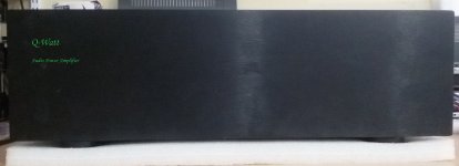
If i may delange (or any other Q-Watt constructor), could you please give me some ideas how i can label my rear panel as you have done in you #382 post, thread page 39?
See Delange's rear panel image
See Delange's rear panel image
Attachments

Last edited:
If i may delange (or any other Q-Watt constructor), could you please give me some ideas how i can label my rear panel as you have done in you #382 post, thread page 39?
See Delange's rear panel image
The panel was constructed by Shaeffer: https://www.schaeffer-ag.de/en/
It is also possible to use their Front Panel Designer software and print the panel on adhésive paper. Apply that label to the panel and the cover it with adhesive plastic foil for extra protection. That's what I did on the design of my first channel (see initial pics).
I've located from the numerous local Graphic Designers to do what Delange suggested and only for about £10, so i'll probably go for it.
Just need to sort out wording, an example ive posted here
Not forgetting that i still have to fit the front led indicator...
Just need to sort out wording, an example ive posted here
Not forgetting that i still have to fit the front led indicator...
Attachments

KiloOhms should have small 'k'. Otherwise it's KelvinOhms...
Is this for machining (etching) of the aluminium or for a stick-on label?
I would prefer to omit the THD specs. I also like using lines to link related connectors say from the word Input to Left and Right.
You could give some guidance on what level of attenuation is provided instead of min/max.
POPS
Last edited:
You could give some guidance on what level of attenuation is provided instead of min/max.
The pot is implemented as a volume, so there are two obvious choices:
1) - infinity to 0 dB
2) 0 to 10
Cheers popchops & delange for your valuable input, points taken.
I've chosen adhésive paper that will be covered with adhesive plastic foil for extra protection.
I've chosen adhésive paper that will be covered with adhesive plastic foil for extra protection.
- Home
- Amplifiers
- Chip Amps
- My Q-Watt project