this does give a lower input impedance, but your maximum output impedance is still ~25% of 50kIf I have a 50K pot with 11K in parallel from the wiper to ground, does this give me 9K Ohms input impedance
If I have a 50K pot with 11K in parallel from the wiper to ground, does this give me 9K Ohms input impedance (for the vol control box) at max vol?
Resistor value of two parallel resistors are calculated as following:
(R1 * R2) / (R1 + R2).
So at max volume yours will be about 8k33.
That is fine. I just don't like high resistor values and a pot of 50k is to high in my book. Remember that there is another disadvantage: since the number of turns on the pot are the same, the amount of resistor change while turning gets larger as the pot value gets higher. It means that the volume is more sensitive to the amount of turning. (I hope it is clear what I'm trying to say).
There is a rule of thumb that says that the input impedance of your device (volume pot in this case) should be at least 10 x the output impedance of your source. So, according to that rule of thumb you should have a pot of no less than 2k5.
Of course, when you fit additional resistors in the input section of your passive pre-amp then these are in series with your volume pot (increasing the total resistor value).
If you want to implement the volume curve as documented by Elliot you could use an active alternative. This way you can keep the resistor value lower. See the attached note from TI.
Attachments
It is not clear. Because you are wrong.................. Remember that there is another disadvantage: since the number of turns on the pot are the same, the amount of resistor change while turning gets larger as the pot value gets higher. It means that the volume is more sensitive to the amount of turning. (I hope it is clear what I'm trying to say)...............
It is the ratio of upper:lower resistances that determines the output.
The RATIO is determined by the rotation, not the absolute values.
Again you are wrong.There is a rule of thumb that says that the input impedance of your device (volume pot in this case) should be at least 10 x the output impedance of your source. So, according to that rule of thumb you should have a pot of no less than 2k5.
The recommended Source:Receiver impedance ratio for effective Voltage transfer is often stated as greater than 1:5, 1:10 is a good value, 1:20 also works, I have even seen 1:1000 and that works as well.
The vol pot acts as a Receiver for the signal coming from the Source. Ideally one requires the rule to apply for this and aiming for > 1:5 is advisable.
The vol pot also acts as the Source when sending a signal to the next stage/Receiver.
Here the output impedance of the vol pot varies and can be as high as the sum of vol pot resistance + previous source impedance divided by four.
Put in some numbers.
Source has output impedance of 200r, Vol pot is 50k, Receiver is 100k
First source:vol pot becomes 200r:50k and meets the minimum of 1:5 (~1:250)
Second vol pot to Receiver becomes {200r+50k}/4:100k and meets the minimum of 1:5 (~1:8)
Repeat the arithmetic for a selection of 20k, 10k, 5k, 2k and 1k vol pots and you will find that they all work and all meet the 1:5 RATIO for good voltage transfer.
Last edited:
attenuation & volume control
Here's the idea:
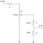
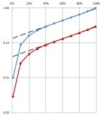
47k linear pot followed by a 9k:21k Ohm voltage divider as shown attached. Blue line shows the calculated voltage transfer Vout/Vin before the voltage divider (input to resistor B). Red line shows voltage transfer with the voltage divider (between resistors B & C). Resistor A was set to zero for calcs.
Should give me the necessary attenuation to protect my speakers while I test the Q-Watt.
Can anybody explain in words of one syllable how to calculate the input & output impedance here?
Is the voltage divider (resistors B & C) a better arrangement for attenuation than a series resister feeding into the pot (resistor A)?
Cheers - Pops.
Here's the idea:
47k linear pot followed by a 9k:21k Ohm voltage divider as shown attached. Blue line shows the calculated voltage transfer Vout/Vin before the voltage divider (input to resistor B). Red line shows voltage transfer with the voltage divider (between resistors B & C). Resistor A was set to zero for calcs.
Should give me the necessary attenuation to protect my speakers while I test the Q-Watt.
Can anybody explain in words of one syllable how to calculate the input & output impedance here?
Is the voltage divider (resistors B & C) a better arrangement for attenuation than a series resister feeding into the pot (resistor A)?
Cheers - Pops.
Attachments
Last edited:
Start by changing each vol pot into two resistors that add up to the pot value.
A=0
B= 46k+1k
C=21k (does not exist in E24)
D= 9k (does not exist in E24)
The output impedance of B is 1k||{0k+46k} = 978r7ohms
The output impedance of C/D = 9k||{978.7+21k} = 6385r3ohms
Input impedance of C/D depends on load impedance. I'll choose 100k for Zin.
C sees D||Zin = 9k||100k = 8256r8ohms = E
B sees C+E = 21k+8256r8 = 29256r8 = F
Upper B (46k) sees LowerB (1k)||F = 1k||29256r8 = 966r9ohms = G
A sees UpperB+G = 46k+966r9 = 46966r9
Input impedance for that one setting = ~47k
Output impedance = ~6k4
Throw that idea in the bin.
Change input vol pot to 10k, insert 0k or 30k for A
This will give a consistent input impedance and a lower output impedance.
The lowest input impedance will be 100k||10k = 9k091, or 30k+{100k||10k} = 39k091
The highest input impedance will be 10k, or 40k
The highest output impedance will be 25%*10k, or 25%*{30k+10k}=10k. This second setting should never be required because you are adding -12dB with the 30k and adding -6dB at the vol pot for a total attenuation of -18dB, A = 0k and B= 8k74+1k26 gives ~-18dB giving an output impedance of 1k1 instead of 10k
Put that into a spreadsheet for almost instant answers.
Last edited:
Change input vol pot to 10k, insert 0k or 30k for A
This will give a consistent input impedance and a lower output impedance.
Hi Andrew,
OK so resistor A is preferable to the C/D voltage divider, as delange recommended before. Got it. Strange that Kevin pointed me towards a voltage divider.
I would like to emulate a 10k logarithmic pot, with a linear pot (B) and a resistor (C). C = B/5. What value of B is needed? Surely not 10k?
Many thanks for the calcs. Pops.
A lin vol pot with a log emulating resistor gives an "S" curve instead of a log curve. (try plotting rotation vs dB attenuation. A straight line is a log law.) You, the Builder, can change the slope of that straight (or bent) line.
But a log vol pot does not give a log curve because most/all are two series connected linear tracks inside the casing.
The usual recomendation for a log emulating resistor is somewhere around 10% to 20% of the pot value. Your /5 is 20%, so may be a bit too high.
It is easy to determine the resistance vs rotation of a linear pot. The only error is in the manufacturing tolerances of the pot build.
Determining the resistance vs rotation of a log law pot must be done by measurement and every pot will be different and every manufacturer will be different. You can only do it for the pot in your measurement jig.
I have used 100k & 15K and 100k & 10k, but neither give good rotation sensitivity. Neither were kept in the music system for very long (a year or so).
I find the ONLY way to get the rotation vs required attenuation is to make up a custom stepper with my own values.
One of the problems with the log emulating lin+R is the VERY variable input impedance. This seriously affects the RF attenuation. At worst you must set the lowest RF frequency attenuation someoctaves above the audio band. But as you rotate to a new setting you can find that the RF attenuation moves a decade higher and allows much RF to pass into the system.
Last edited:
Hi folks.
Quick question to Calpe and Delange and the other Q-Watt builders:
Can anybody summarise the isolation requirements for the semiconductors T1-T5 on each heatsink. It looks to me like there is in each case a metal bolt holding the chips onto the heatsink. I know theres a non-conductive pad... but the screw passes through it.
So... how do I avoid unintentional 55V on my heatsink and am I missing something? Is it correct to connect my heatsinks to earth?
T2 has the metal bolt directly holding the base of the chip? So is this at 0 volts? Other than an isolating pad under each chip, what extra measures are needed. (Some small black washers were included in the kit. What are these for? How many should I have?)
Am ready to solder the chips and IC2 and filter caps now. Thanks, Pops.
Attachments
Can anybody summarise the isolation requirements for the semiconductors T1-T5 on each heatsink. It looks to me like there is in each case a metal bolt holding the chips onto the heatsink. I know theres a non-conductive pad... but the screw passes through it.
So... how do I avoid unintentional 55V on my heatsink and am I missing something?
Only T2 and T3 need a plastic bushing before fixing the transistors. The other transistors have a plastic housing and these don't need that isolating bushing.
It is important that the holes are drilled at the correct locations so that the transistors sit nicely above their places on the PCB.
This video (at the end) shows how to mount the transistors and which ones need the isolating bushing:
https://www.youtube.com/watch?v=7pPDXuZxAg8
Is it correct to connect my heatsinks to earth?
Yes.
I did that too and it works fine. The metal enclosure needs to be earthed anyway (for safety reasons).
T2 has the metal bolt directly holding the base of the chip? So is this at 0 volts? Other than an isolating pad under each chip, what extra measures are needed.
The heatsink is at -55 volts if you screw it directly to the heatsink.
That is fine; just do not touch the heatsink while the amp is powered on. In normal circonstances no one will be able to touch it because the enclosure will be closed. As a precaution I wrote it on the heatsink with a alcohol marker. If some one in the future opens the enclosure the that person will notice the warning.
(Some small black washers were included in the kit. What are these for? How many should I have?)
I believe these are the two isolating bushings for T2 and T3.
Am ready to solder the chips and IC2 and filter caps now. Thanks, Pops.
Almost there !
Popchops, glad to hear your a step closer.
Taken from the Elektor article:-
'Mount the heatsink so that it is a bit above the board when the IC is fitted, to avoid contact with R1, R4 and R5. Caution: the metallic rear surface of the IC is connected to the negative supply voltage. This means that if you do not use insulated mounting hardware, the heatsink will be at the negative supply voltage. For safety, we recommend using insulating mounting hardware here.'
In my case i chose to fit a insulating pad that covers the metal part on the rear of the i.c., i prefer not to have -55v on the heatsink.
Check carefully the bottom of the heatsink does not/will not make contact with R1, R4 & R5.
Delange & i have our ears open.....waiting for your Q-Watt
Last edited:
Thanks All. Am off camping this week and then I have the following Monday off work to 'finish off' the Q-Watt.
Calpe - I wasn't planning to isolate the small 8cm heatsink... I prefer to maximise cooling. I will have to put some warning inside the case.
Pops
Calpe - I wasn't planning to isolate the small 8cm heatsink... I prefer to maximise cooling. I will have to put some warning inside the case.
Pops
Thanks All. Am off camping this week and then I have the following Monday off work to 'finish off' the Q-Watt.
Life is all about priorities 🙂
Enjoy the holidays !
That's fine popchops, that's the pleasure with us Q-Watt builders, each one of us has our own thoughts and ideas.
Just double check the bottom of the heatsink is clear from those resistors mention before.
Enjoy break get plenty of rest to blow out your neighbours when you get back!😉
Just double check the bottom of the heatsink is clear from those resistors mention before.
Enjoy break get plenty of rest to blow out your neighbours when you get back!😉
Thanks. And another thing, just so I have all my ducks in a row: what voltage should I be looking for across the 47R resistors during setup? If I want I = 0.030 A and V = IR then V = 1.41 V drop across the resistor?
Is this right?
Is this right?
Thanks. And another thing, just so I have all my ducks in a row: what voltage should I be looking for across the 47R resistors during setup? If I want I = 0.030 A and V = IR then V = 1.41 V drop across the resistor?
Is this right?
You first need to measure the voltage across the 47 ohms resistor (in the positive lead) when the speaker relay is activated. From that voltage you calculate the current (I = U / 47). Add 30 mA to that result and then calculate the correct voltage (U = I x 47). Next, turn P1 until you reach that voltage across the 47 ohms resistor.
I don't remember the exact figures but this is how I did it.
Later on, when I removed the 47 ohms resistors I verified the current though resistors R10 and R11 and the bias current was spot on. This shows that the above method works very well.
Go by what delange advises, his Q-Watt is up and running, it was in his hands when he begun and i'm sure it sounds as my Q-Watt that was also put in my hands and also sounds terrific.
Elektor states the following (i did this setup): -
To do this, first connect two 47 Ω, 5 W power resistors in series with the positive and negative supply voltage terminals.
If you have a dual Q-Watt i.e. Left and Right channel, set up one channel first.
Connect an ammeter (working) in series with the positive supply line. Before switching on the supply voltage, turn P1 fully counterclockwise
After the power is switched on, the current through the positive supply line should be approximately 30 mA when the output relay is engaged. If not slowly turn P1 to the right (clockwise) until you set it to 30mA.
With the initial switch on, the Q.Current will be high but drops quickly and with your meter in series with the +Ve supply it lowers after switch on, so then set your meter to a 0-100mA range, you'll be able to adjust the Q.C. spot on to 30mA.
Delange and I have our ears tuned for the popchops Q-Watt....
Last edited:
Hi Guys!This video (at the end) shows how to mount the transistors and which ones need the isolating bushing:
https://www.youtube.com/watch?v=7pPDXuZxAg8
This Elektor vid shows a very thin film being peeled away from the Kapton 'insulating washers' / thermal pads before mounting on the main heatsink.
I cannot seem to find/remove any such film. Did anybody else have a problem here? Is it on both red and blue pads? Very frustrated... Pops.
Hi Guys!
This Elektor vid shows a very thin film being peeled away from the Kapton 'insulating washers' / thermal pads before mounting on the main heatsink.
I cannot seem to find/remove any such film. Did anybody else have a problem here? Is it on both red and blue pads? Very frustrated... Pops.
Mine didn't have those plastic film things either.
Probably Elektor used different ones in the beginning. I wouldn't worry about it.
- Home
- Amplifiers
- Chip Amps
- My Q-Watt project