you definitely switched primary and secondary
post picture of your soft star, with clear connections, so e can check what you did and point you in right way
post picture of your soft star, with clear connections, so e can check what you did and point you in right way
Following the Firstwatt psu circuit diagram for 240V:
The softstart is placed in series between the 2 primary windings, assuming you had dual primaries.
The softstart is placed in series between the 2 primary windings, assuming you had dual primaries.
Methink it's confusing but correct...
Ok then, so.
Apologies for my ignorance and confusion.
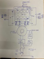
I tried to make a sketch how everything is connected, and afaik it’s all there (haven‘t forgotten anything).
I not able to draw it as a true scm, so it’s a bit of a kindergarden attempt...
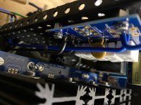
the 2 Fotos show:
1) The connection from the mains (after the switch) into softstart resp. to speakerdelay. (The speakerdelay is not connected to the softitart-board but just uses it as connection-point. This looks confusing, I did it for lazyness)
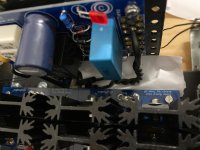
2) The connection FROM the softstart TO the toroid's primaries. (Paper is there for visibility)
PS: I had all PSU-parts already switched on, everything seems fine so far: Softstart engages (quick, may need a longer delay), PSU gives 24.8V I believe... Speaker-delay got tested under the sharp eyes of mooly, all good there.
(Please don't read this: Basically, I'm confident it is all well here 😎 )
Ok then, so.
Apologies for my ignorance and confusion.
I tried to make a sketch how everything is connected, and afaik it’s all there (haven‘t forgotten anything).
I not able to draw it as a true scm, so it’s a bit of a kindergarden attempt...
the 2 Fotos show:
1) The connection from the mains (after the switch) into softstart resp. to speakerdelay. (The speakerdelay is not connected to the softitart-board but just uses it as connection-point. This looks confusing, I did it for lazyness)
2) The connection FROM the softstart TO the toroid's primaries. (Paper is there for visibility)
PS: I had all PSU-parts already switched on, everything seems fine so far: Softstart engages (quick, may need a longer delay), PSU gives 24.8V I believe... Speaker-delay got tested under the sharp eyes of mooly, all good there.
(Please don't read this: Basically, I'm confident it is all well here 😎 )
Attachments
........
PS: I had all PSU-parts already switched on, everything seems fine so far: Softstart engages (quick, may need a longer delay), PSU gives 24.8V I believe... Speaker-delay got tested under the sharp eyes of mooly, all good there.
(Please don't read this: Basically, I'm confident it is all well here 😎 )
so what's the problem, then?
quick look at pic sez everything is OK, just take care of damn small xformer - 2R reading is sure sign that you connected it backwards
looks good so far...
ZM, Pico,
I checked it all, made the corrections (wiring details), checked again that primaries/secondaries etc. are all where they belong, grounds connected.
(had to hold my breath) hooked it up with light-bulb tester and nothing went off.
Light-bulb went on (not too bright) and dimmed down to dark/unvisible.
softstart-relay switched on smoothly, delay was ~ 0.6 - 08 sec.
speaker delay relays switched on smoothly, delay ~ 4-5 sec.
measured the rails (first with, then without lightbulb-checker): with 23.something, without 24.59 stable, both channels 🙂
These are good signs, aren't they?
Last edited:
this time something's weird...
HA!
All connected, LED's are all on (need to adjust brightness of the softstart-lights though but that's not to bother you.) which made me expect success.
but: there's plain bold 0000.0 across the source resistors. both channels. (A as well as mA).
offset is adjustable but very jumpy between <1 and >-1 mA.
PSU seems ok, I get +/- 24.6V on both channels...
Last edited:
If no voltage across source resistors, the amplifier is not turning on. Do the F4 boards have power?
Yes!
24.6V on all in+ - gnd and in- - gnd both boards.
Led are gently glowing, too
(And take very long—a minute or two—to get off, just as the PSU‘s)
(Thanks for chiming in 🙂, and I‘m grateful for tips and pointers but won‘t see my baby until monday afternoon 🙁 )
24.6V on all in+ - gnd and in- - gnd both boards.
Led are gently glowing, too
(And take very long—a minute or two—to get off, just as the PSU‘s)
(Thanks for chiming in 🙂, and I‘m grateful for tips and pointers but won‘t see my baby until monday afternoon 🙁 )
Last edited:
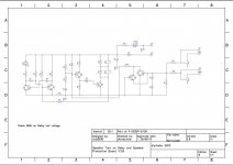
scm and thoughts
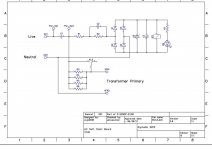
Here are the schematics of the goodies I built.
They are the plain originals straight from the diyaudiostore...
I must say that I did not rely on them for the build.
I had the boards and the BOMs, and (almost😀) blindly trusted the community...
I don't know, but, what strikes me is that both channels behave exactly the same: power goes properly(?) to the channels, I can manipulate offset and leds are alight...
Then, the helper-boards Soft-Start and Speaker-Delay seem to work fine, but ...
Attachments
Last edited:
Did you try adjusting P1? What's the max voltage you can get across the anode and cathode of Q11 by adjusting P1?
Please confirm the part you used for Q11 and your value for R8.
Please confirm the part you used for Q11 and your value for R8.
Ok, will check this—on monday presumably.
(My wife just ruined her knee when she slipped avoiding a snowball, so weekend-program is dodo/messed up.)
(My wife just ruined her knee when she slipped avoiding a snowball, so weekend-program is dodo/messed up.)
AFAIK, I used NCP431ACLPRAG @ Q11
(That's according to my mouser order-history.)
Not able to verify onboard or to take measurements yet.
(That's according to my mouser order-history.)
Not able to verify onboard or to take measurements yet.
part looks good, according to datasheet (stable with 40uA)
ref. to sch. you posted in #34, change R9 from 10K to 8K2 and, if everything else is good - you will be able to set Iq
ref. to sch. you posted in #34, change R9 from 10K to 8K2 and, if everything else is good - you will be able to set Iq
- Home
- Amplifiers
- Pass Labs
- My F4 build (questions, bragging, and other thoughts)