one of the receiptsWhere are the receipts?
Attachments

As Graham Maynard pointed out, the sound quality depends on the first period distortion (FCD). According to Jiri Dostala's classification, the main contribution to FCD is made by speed distortions. In turn, Cyrill Hammer noted in an interview that amplifiers with GNFB should have a tPD of only a few ns, if you are not able to fulfill this condition, then make amplifiers without GNFB. Moreover, for the latter option, he did not stipulate what the Group Delay should be.
Let's try to figure it out with a specific example.
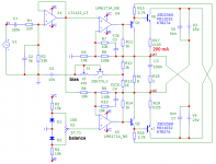
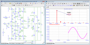
GainWire-NGNFB-classB-PowerAmp
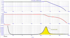
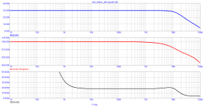
It can be seen from the Bode diagram that tPD = 114 ns. Group Delay is constant almost up to 200 kHz, then there is a smooth decline !!!
The spectrum of harmonics of a signal with a frequency of 20 kHz is short, only one 2nd harmonic at a level of 0.046%. It is known that with a short spectrum the level of the 2nd harmonic can be several percent without negatively affecting the sound quality (as an example: most tube amplifiers). Let's measure the vector errors using the Hafler test. With an output voltage of 35 V, vector errors are 0.5 V, i.e. 70 times lower (~-37 dB) (middle graph).
We will measure all types of distortions, for this we subtract from the input voltage delayed for a time tPD and adjusted to the output voltage level (lower graph). Here we see the 2nd harmonic at a level of 0.046% and velocity distortions of negligible magnitude. As shown by the test performed, the speed distortions, even at tPD = 114 ns, are much lower than the nonlinear distortions. The same value is confirmed by the calculations of Jiri Dostal.
As practice shows, this value is also true for amplifiers with GNFB, provided that the Group Delay has a constant value up to at least 200 ... 300 kHz and then a smooth decline occurs (without overshoot as in the Hafler XL-280 amplifier).
Let's try to figure it out with a specific example.
GainWire-NGNFB-classB-PowerAmp
It can be seen from the Bode diagram that tPD = 114 ns. Group Delay is constant almost up to 200 kHz, then there is a smooth decline !!!
The spectrum of harmonics of a signal with a frequency of 20 kHz is short, only one 2nd harmonic at a level of 0.046%. It is known that with a short spectrum the level of the 2nd harmonic can be several percent without negatively affecting the sound quality (as an example: most tube amplifiers). Let's measure the vector errors using the Hafler test. With an output voltage of 35 V, vector errors are 0.5 V, i.e. 70 times lower (~-37 dB) (middle graph).
We will measure all types of distortions, for this we subtract from the input voltage delayed for a time tPD and adjusted to the output voltage level (lower graph). Here we see the 2nd harmonic at a level of 0.046% and velocity distortions of negligible magnitude. As shown by the test performed, the speed distortions, even at tPD = 114 ns, are much lower than the nonlinear distortions. The same value is confirmed by the calculations of Jiri Dostal.
As practice shows, this value is also true for amplifiers with GNFB, provided that the Group Delay has a constant value up to at least 200 ... 300 kHz and then a smooth decline occurs (without overshoot as in the Hafler XL-280 amplifier).
Attachments

Last edited:
Something is wrong with your schematic and simulation.
In my simulation at 20 Vef 20 kHz at the output second harmonic is less than 0.0001% and total THD is 0.0006%.
In my simulation at 20 Vef 20 kHz at the output second harmonic is less than 0.0001% and total THD is 0.0006%.
Something is wrong with your schematic and simulation.
In my simulation at 20 Vef 20 kHz at the output second harmonic is less than 0.0001% and total THD is 0.0006%.
Got an .asc perhaps? As those numbers get me a little aroused .. 😀
Here's another Banksy ...
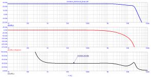
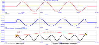
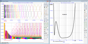
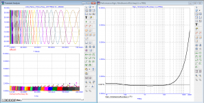
It can be seen from the Bode diagram that Group Delay has a negative value in almost the entire sound band, and immediately after the sound band it begins to grow and reaches 610 ns by the frequency of 350 kHz.
In the steady state, the lead of the output signal with respect to the input is 20 ns.
The vector error (SWDT) is less than 100 mV, taking into account the severe distortion of the waveform.
In order to measure all types of introduced distortion, it is necessary to delay the output signal by 20 ns. The measurement result is shown in the lower graph.
The graph shows that the amplitude of speed distortion reaches 0.35 V, the peak level exceeds 1%.
This is another example as an addition to the Hafler XL-280 amplifier tests.
Attachments
I simulated INS without output buffer.
Damir
Im not sure why on earth you choose to simulate the amplifier without the outputstage, but run a simulation of only the frontend (IPS and "VAS") and saying that the amp has close to 1ppm distortion.
Stein
Last edited:
Here's another Banksy ...
No.
You have chosen to "analyse" Jan's HEC amplifier and are trying to show how bad it is in your opinion.
Your analysis is far out.
Stein
No.
You have chosen to "analyse" Jan's HEC amplifier and are trying to show how bad it is in your opinion.
Your analysis is far out.
Stein
Stein, what is your claim based on? A statement without arguments is unfounded.
Just don't show me the THD measurement results with the Audioprecision
Im not sure why on earth you choose to simulate the amplifier without the outputstage, but run a simulation of only the frontend (IPS and "VAS") and saying that the amp has close to 1ppm distortion.
Stein
Because petr did it the same way and want to tell his simulation is not correct.
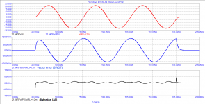
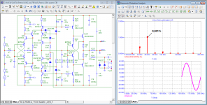
Despite the beautifully presented theory, the parameters of this solution are far from perfect.
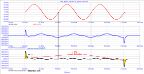
The passband drops abruptly above 300 kHz.
Beginning with a frequency of 2 kHz, distortion increases sharply.
when measured in the 2nd period, everything is much worse
The passband drops abruptly above 300 kHz.
Beginning with a frequency of 2 kHz, distortion increases sharply.
when measured in the 2nd period, everything is much worse
Attachments
Petr, don't you understand that if you want to make a point, but you constantly change the subject of your investigation, your statements are totally worthless?
Why do you continue to do exactly what a sensible technical investigation is NOT? Do you think that if you fail to convince us with amp A, if you do exactly the same thing with amp B all of a sudden we magically are convinced??
You are in the business here to convince us of an important technical point that we have missed until now, right?
So it is your task to communicate with us, to speak our technical language, to present your data in such a way that we can easily understand.
For the last several years you have totally failed in your task, mainly because you refuse to explain what you are trying to prove and because you refuse to try to address it in a step by step way we can follow and understand. And then discuss, with lots of smart people here, and be prepared to have to say, yes, maybe I was not right at this or that point. Only in such a way does our understanding progress. Instead, you throw up graphs full of unusual terms and change the subject of your investigations constantly. If we don't 'get' it, the solution is not to call us stupid. The solution is to realize you failed and try to do better.
But maybe you are a masochist?
Jan
Last edited:
Jan,
East is east and west is west and never the twain shall meet, so why bother ?
Nothing here like in a ballad to take seriously.
😀 😀
Hans
East is east and west is west and never the twain shall meet, so why bother ?
Nothing here like in a ballad to take seriously.
😀 😀
Hans
Jan, more than 15 years ago Graham Maynard tried to explain to you the secret of correlating amplifier parameters with sound quality. But you didn’t understand anything then, you don’t understand it even today. You don't understand standard charts (which is very sad). I have repeatedly given links to sources on the theory that I am guided by. But it seems useless for you to explain anything.
I specifically cite different circuits with the same tests, so that after understanding the tests using the example of one amplifier, you can understand the relationship between the parameters.
I repeat once again that speed distortions are responsible for the sound quality, which appear at the moments of dV/dt change.
Here is a variant of a voltage amplifier without GNFB, compare with the parameters of your amplifier for a similar purpose.
As you can see, there is no speed distortion in this amplifier as such!
Attachments

@petr_2009,
Please stop the ad hominem attacks, it doesn't help with getting your point across, quite the contrary to be exact.
Also, you seem to be posting new designs every day, and honestly 'm not going to invest my time into something that's constantly in flux. So please settle on one design which you feel is the epitome of proper amplifier design and we'll go from there.
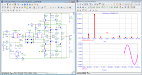
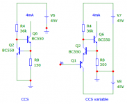
I hope that you will understand everything from the given figureWhat are Q2 and Q4 good for ?
Attachments
Jan, unlike you, I am not engaged in blah, blah, blah and insults of opponents and their constant humiliation (which you allowed yourself with both Graham Maynard and me), I give specific arguments in the form of tests of specific schemes.
Using specific examples, I have shown that the accuracy of amplification depends on the group delay time and is very important - on its behavior behind the audio band (see the test of the Hafler XL-280 amplifier and voltage amplifier from AudioXpress 2008 08-09).
On tests with the help of burst, I showed the physical meaning of the distortions of the first period (FCD), and also showed what the essence of speed distortions is.
In amplifiers without GNFB, there is practically no speed distortion (I gave a few examples).
Amplifiers with GNFB must have a Group Delay of no more than 100 ... 120 ns, provided that it is constant in a band of at least 200 ... 300 kHz and then has a smooth falloff.
That's actually all that needs to be learned.
- Home
- Amplifiers
- Solid State
- Musings on amp design... a thread split