It seems you have learned something, to show your speed errors, you should limit the BW of your signals with just a few cycles to the BW where the GD is flat.
For the 250Khz BW amp shown here having a flat GD of 620nsec, this signal should be limited to 20Khz max.
The 100nsec that you mention is 5 to 6 times faster, only possible with a 1.5Mhz BW amp, completely insane and over the top.
I propose as an exercise to use this simple amplifier and show all your pictures with vector error, speed error etc. etc.
Then we can analyse, because a linear filter process has no distortion.
And please don't start with an another subject, just do this for a change.
Hans
.
Hans, draw a model of the simplest amplifier and practice measuring parameters. That you drew some kind of garbage, I'm sorry for the expression. There will be difficulties, contact me, I will help you figure it out ...
But in music signals there are no pure sinusoids, there are chaotically changing impulse signals
Here's another Fourier denier. This breed seems to flourish nowadays.
Last edited:
Petr,
Just to show what non information you are trying to present to us, I took an 500Khz BW "amplifier" with a gain of 25.
Obviously you didn't dare to take the challenge, that's why I did it.
This distortion free Amp has a perfect flat 310nsec GD as can be seen in the first image.
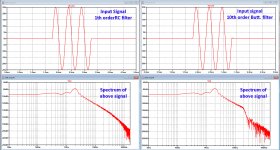
Input signal with three 2Khz sine waves was filtered resp. with a first order RC filter and with a 10th order Butterworth filter, both having their -3dB point at 20kHz.
See second image with filtered input signal and its spectrum.
RC filtered left and 10th order Butt. filter at the right.
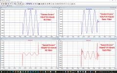
Third image shows the so called Vector errors and Speed errors.
Both errors are largely dependant on the used filters, and since none of both is a brick wall filter, some of the higher frequencies with a different GD are slipping through the filter, leading to so called "Speed Errors" that have no meaning at all, just as the Vector Errors are supposed to show something that is depending on the used input filter, but also meaning nothing at all.
So this all proves that a perfect amp with no distortion can be disqualified by silly test patterns generated by not adequately filtered input signals.
Hans
.
Just to show what non information you are trying to present to us, I took an 500Khz BW "amplifier" with a gain of 25.
Obviously you didn't dare to take the challenge, that's why I did it.
This distortion free Amp has a perfect flat 310nsec GD as can be seen in the first image.
Input signal with three 2Khz sine waves was filtered resp. with a first order RC filter and with a 10th order Butterworth filter, both having their -3dB point at 20kHz.
See second image with filtered input signal and its spectrum.
RC filtered left and 10th order Butt. filter at the right.
Third image shows the so called Vector errors and Speed errors.
Both errors are largely dependant on the used filters, and since none of both is a brick wall filter, some of the higher frequencies with a different GD are slipping through the filter, leading to so called "Speed Errors" that have no meaning at all, just as the Vector Errors are supposed to show something that is depending on the used input filter, but also meaning nothing at all.
So this all proves that a perfect amp with no distortion can be disqualified by silly test patterns generated by not adequately filtered input signals.
Hans
.
Attachments

Jan, I brought Williamson's point just to emphasize once again that THD less than 0.1% does not mean an improvement in sound quality. The number of zeros after the decimal point does not mean absolutely anything.
Oh come you really can do better than that - very low distortion is your guarantee that there's a lot of negative feedback, which means the amp's response is set by the feedback network (which being usually a resistor divider is linear and delayless).
Thus you know the phase response / group-delay is primarily that of the input shelving filter and output network, both of which should be well clear of the audio band. So yes you have to check the response is flat across the audio band, I suppose you _could_ build a resonant 1kHz amplifier and say "0.0001% THD at 1kHz" - but I don't think that sort of trickery is what we're talking about here.
Ideally you have a graph of distortion v. frequency and distortion v. amplitude, which tells a much fuller story, but if you have an amp that's say <0.01% across the board you'd be hard pressed to find faults with its response to any plausible audio signal, the maths of Fourier analysis (and more generally wavelet analysis) are solid and apply to reality. Certainly any low distortion amp is going to contribute negligible issues compared to a speaker driver's response (which you have alluded to)
If you have the figure as a SINAD value you also have a limit on the amount of noise produced by the amplifier.
Of course when the feedback network is more complex (RIAA compensation for instance), low THD just means low THD. But again that's not what we are talking about surely?
Jan, I brought Williamson's point just to emphasize once again that THD less than 0.1% does not mean an improvement in sound quality.
Yes but in the same sentence you say it is not the case for modern transistor amplifiers.
You said:
"Back in the 50s of the last century, Theo Williamson wrote that for high-quality amplification of an audio signal, it is enough that at maximum power THD was no more than 0.1%. In this case, the content of harmonics is virtually undetectable in the most sophisticated listening tests (obviously he meant short-spectrum tube amplifiers, this does not apply to modern transistor amplifiers)." (bold mine)"
So what is it?
Jan
Last edited:
Submissions by petr_2009 fail common sense, let alone engineering scrutiny. Group delay is trashed from the start, beginning with the microphone. It is then subjected to egregious anomalies by DACs and loudspeaker crossovers. The idea that an amp will affect sound quality through this mechanism, is fanciful.
Class D amps are now competing technically and gathering advocates for sound quality at bandwidths of 45KHz and 60KHz, inconveniently for petr_2009.
John Curl stated that if an inductor is not fitted, the slew rate should be limited for obvious and practical reasons. Reasons petr_2009 fails to comprehend. The arrayed talents of Baxandall, Cordell, Curl, and Jung got it all wrong.
Faster amps require better phase margins, but petr_2009 has no suggestions how that might be achieved. By contrast, forum members, dadod etc. provide skilled, complete, engineering solutions.
In a desperate bid to appear erudite, petr_2009 refers to a paper by David Griesinger. This paper is about the intelligibility of speech and localization of sound in stereo recordings. The highest mentioned frequency is 8KHz, including harmonics, and no requirement for extended bandwidth.
If it's not difficult, can you tell me where you can get acquainted with his words? It would be interesting to know the reasoning.John Curl stated that if an inductor is not fitted, the slew rate should be limited for obvious and practical reasons. Reasons petr_2009 fails to comprehend. The arrayed talents of Baxandall, Cordell, Curl, and Jung got it all wrong.
You will have to search the threads on inductors. It was a long one. The reason is simple. Reactive load current needs to be limited to prevent saturation of output devices and possible oscillation. In other words, you need to protect the amp as if it had an inductor.
Nothing is for free.
Nothing is for free.
It seems you have learned something, to show your speed errors, you should limit the BW of your signals with just a few cycles to the BW where the GD is flat.
Hans
.
Hans, I kind of told you clearly: type in a model of a real amplifier (maybe you have your own designs) and run tests. If something doesn't work out, I'll help you figure it out ...
Hans, I kind of told you clearly: type in a model of a real amplifier (maybe you have your own designs) and run tests. If something doesn't work out, I'll help you figure it out ...
Why don't you simply comment on posting #883.
This is a real amp's model, but it shows the importance of the used filter for filtering the input signal.
So when you want to prove something, you should also show the FFT of the used 3 wave input signal.
When it's spectrum doesn't stop abruptly at the point where the GD stops being flat, you are cheating yourself.
And when I need your help, I will certainly ask you, but don't expect this to happen, first do your own homework in a decent way.
So I'm waiting for you to show us an FFT of your input signal.
If you are unable to brick wall filter the used input signal, I will be happy to provide you with one, then we'll talk further.
Hans
Hans, I don’t need to show the linear distortion introduced by filters. If you paid attention, I test all amplifiers without an input RC filter in order to see the distortions introduced by the amplifier itself, but I process the signals with a first-order low-pass filter with a cutoff frequency of 100 kHz (as in the DIM-100 tests).Why don't you simply comment on posting #883.
Hans
In the third graph, you demonstrate distortion, but you did not even realize that there should be no signal in the middle of the burst (there should be full compensation!), Since your amplifier is perfect. Now send a signal with a frequency of 10 kHz to the same circuits and show what will happen on the 3rd graph.
Hans, why in your circuit an ideal amplifier with Ku = 25 if you are measuring filter distortion. What are you trying to prove to me with this?
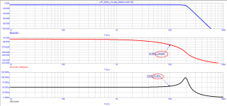
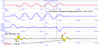
Here is the Bode diagram of your filter. It can be seen that the output signal at a frequency of 10 kHz is rotated by more than 180 degrees, (approximately in antiphase as seen in the next figure), the signal is delayed by more than 50 μs.
You can imagine what will happen to the signal closer to the frequency of 20 kHz.
Jan, have you been looking for a reference DAC circuit for too long, or don't you know what it is? All you need is its filter, or at least its characteristics.
Attachments
Last edited:
If you think that the square wave signal you showed is what comes out of a DAC, you are a lost cause.
Why would I tell you another DAC and you show me again this non-existing square wave? You're just wasting my time.
Jan
Why would I tell you another DAC and you show me again this non-existing square wave? You're just wasting my time.
Jan
If you think that the square wave signal you showed is what comes out of a DAC, you are a lost cause.
Why would I tell you another DAC and you show me again this non-existing square wave? You're just wasting my time.
Jan
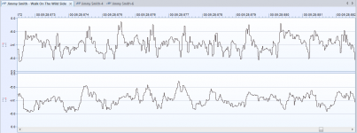
Jan, I didn't think you were that far from digital recording. Here is a snippet of the signal recorded in the CD standard (44.1 kHz, 16 bit) from the audio editor. In this form, it enters the DAK - a converter that converts current into voltage. The converter contains a filter that brings the signal to sound with additional phase and amplitude distortions.
Jan, you can count the steps - there are exactly 44 in 1 millisecond
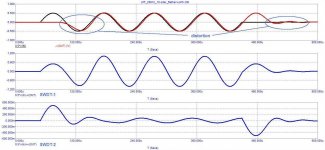
Hans, if you wanted to show me the distortion introduced by a 10th order Butterworth low pass filter with a cutoff frequency of 20 kHz, then at a frequency of 10 kHz they are equal to 15 to 20%.
As you can see, linear distortions are not earlier than after 2 and a half periods.
Attachments
Watch this, for the first 9 minutes - he explains it better than I can.
D/A and A/D | Digital Show and Tell (Monty Montgomery @ xiph.org) - YouTube
Jan
D/A and A/D | Digital Show and Tell (Monty Montgomery @ xiph.org) - YouTube
Jan
Last edited:
Excuses, excuses and endless excuses as expected instead of trying to learn something from a simple model.
I'm sorry to say, but this time you have clearly shown a total lack of basic understanding with astonishing little idea what you are doing.
The type of filters that I used are not playing any role at all apart from the only and single condition that after filtering the input signal should have no frequencies above the point where the GD stops being flat.
If so, there will be no "speed errors" that were still clearly visible in #838.
So looking at the phase and GD of a 10th order Butt. filter is completely senseless.
Using your first order filter, as I already suspected, does not fulfil the above condition at all and leaves the door wide open for higher frequencies having other GD's leading to the "speed errors" that you permanently show.
When increasing the BW of the amp but leaving the input signal the same, you will more and more fulfil the condition that there are no frequencies in the input signal above the flat area of the GD.
That's why you come with those insane BW requirements for an amplifier.
Don't you see the ridiculousness of having a preamp with a BW of 200Khz or even less followed by an amplifier with a BW in the MHz, followed by speakers only capable of reproducing slightly above 20Khz?
As already mentioned several times in previous postings, you are producing non information, unfortunately without realising what you do, but you are too stubborn to listen to others and admit your errors.
Hans
Hans, to what frequency does the Butterworth 10th order LPF have a flat GD?
The next question is: what filter do you think should be used to test amplifiers in the entire audio band?
I have shown what real distortion a 20 kHz filter introduces into a 10 kHz signal. And do you seriously think that now any amplifier is capable of amplifying such a signal without additional distortion?
Last edited:
Since there are no good enough reasons to kick out this petr_2009 character and stop his stinkin’ pollution across multiple threads, don’t you think guys it’s time to stop feeding the troll? Can’t we just ignore him, hoping he’ll drown in his own pile of steaming bull chips?
I know I can, except for this message 😀.
I know I can, except for this message 😀.
- Home
- Amplifiers
- Solid State
- Musings on amp design... a thread split