I showed you in #714 and #716 that (gain*In + delay) minus (Out) has no meaning when the GD is not constant over the input signal’s frequency span.
Subtracting a wide frequency span input signal, because of a sudden start and stop, from an output signal with a changing GD, because of an output choke, will produce non information.
That’s exactly what you are doing, making your Speed Distortion into a meaningless concept.
But as usual, you never respond to examples proving your misconceptions.
Hans
Hans, as far as I understand, you do not understand the meaning of the Hafler SVDT test, as well as the Carver test. When you figure it out, then you will understand the meaning of my tests.
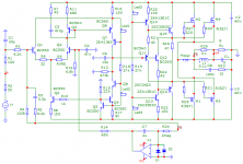
For Ssassen, here's another variation on a simple amplifier circuit. Everything has already been invented long before us, all that remains is to configure it correctly.
For Ssassen, here's another variation on a simple amplifier circuit. Everything has already been invented long before us, all that remains is to configure it correctly.
Attachments
Ha,ha, when you can’t defend a concept, your strategy is always to tell that the other person isn’t smart enough to understand the concept.
Has it ever came to your mind that a person who isn’t even able to defend a concept is likely to telling nonsense.
Don’t hide yourself behind the Haflers and the Carvers of this world, they can defend themselves, but prove that you know what you are talking about.
Stop telling nonsense about speed errors when you do not even understand what BS it is to subtract a fixed timing from a moving target.
Hans
If propagation delay is so damaging, why do fifty year-old recordings still sound so good?
Think about it.
Think about it.
Ha,ha, when you can’t defend a concept, your strategy is always to tell that the other person isn’t smart enough to understand the concept.
Has it ever came to your mind that a person who isn’t even able to defend a concept is likely to telling nonsense.
Don’t hide yourself behind the Haflers and the Carvers of this world, they can defend themselves, but prove that you know what you are talking about.
Stop telling nonsense about speed errors when you do not even understand what BS it is to subtract a fixed timing from a moving target.
Hans
The first recordings were performed either without electronic amplifiers (so they sound the most natural, despite the imperfection of the recording mechanisms), or on tube equipment without NFB. And although at that time the recording equipment (tape recorders, etc.) was far from perfect, nevertheless, many recordings still sound great today. The transition to equipment based on imperfect op amps immediately exposed its shortcomings. Therefore, the recordings made during the transition period sound the least natural. John Curl writes about this in his notes (2006).
On the subject of amplifier concepts, I have already quoted Hammer's statement, let me remind you again:
«Perfect performance in the time domain is no less important. This is especially true of amplifiers based on negative feedback. The theoretical concept of negative feedback is very powerful, and the simplified mathematical equations describing this concept do hold true. But they are only valid if the design addresses the limitations of the concept. The time delay from input to output must be zero! Obviously in real life this is not possible. There are two ways to deal with this problem. Either you just do not apply any negative feedback at all to your design (while giving up the advantages of the concept) or you do speed it up to the level (200 MHz in the case of the Soulution 700 and 710) of a few nanoseconds of time delay from input to output, where timing errors are so small that they do not have any audible impact on the sound. Once you decide to go the latter way a whole bunch of new challenges suddenly arise. Thermal conditions, stability of supply voltages, high-frequency designs, noise induction etc., etc.» (TAS_AmpDesignerRoundtable2012)
Hans, as far as "my concept" is concerned, this is not my concept, it was known about 70 years ago and defended by his doctoral dissertation by Sapozhkov in 1954 and published in 1956. Later, almost 20 years later, Baxandall published the same thing. But as Hafler noted, the compensation of phase errors is unacceptable, since in this case temporal distortions and distortions associated with amplitude-phase conversion drop out. Therefore, in the models when testing, I use the ideal delay line, what is not clear?
Attachments


Words, just words.Hans, as far as "my concept" is concerned, this is not my concept, it was known about 70 years ago and defended by his doctoral dissertation by Sapozhkov in 1954 and published in 1956. Later, almost 20 years later, Baxandall published the same thing. But as Hafler noted, the compensation of phase errors is unacceptable, since in this case temporal distortions and distortions associated with amplitude-phase conversion drop out. Therefore, in the models when testing, I use the ideal delay line, what is not clear?
That someone mentioned something in the past, doesn’t mean it is true.
In the 1800’s there were professors who could “prove” that when a car would go faster as a horse could run, you would drop dead behind the steering wheel.
Others “proved” and some still believe that our world is flat.
Only concepts that are proven to be true in a scientifically responsible way and that are repeatable by others in the same way may be used as facts.
But even then, how many times do we discover that so called “proven concepts” were based on false assumptions.
You can to refer to studies or articles but be aware that lots of this is whisfull thinking, so don’t take everything for granted that fits your theories.
Don’t become a flatlander, try to prove things yourself instead of showing others feathers.
Hans
We should put Joe R, Petr_009 and Martin Colloms (the guy that claimed feedback goes around and around in a Stereophile article) in a room where they can discuss their alternative realities together.
The basic argument is always the want of desired distortion from some and the want of others who want the lowest distortion attainable. Wanted distortion is based on personal perception of sound, which is impossible to measure and assess objectively.
I think, this discussion can be more objective if, the various circuit additions to introduce wanted distortions are also accompanied by the wanted harmonic content they cause. For instrance, let us say circuit addition/modification X, cause the second harmonic f2 to be equal to 2% of the fundamental, the third harmonic f3 to be equal to 5% of the fundamental, etc.
I used raw percentages not decibels, although the latter are equally applicable.
The mistake of Sapozhkov, Baksandall, Akulinichev and other researchers is as follows:
they tried to fit the amplitude-phase characteristics of the input signal to the characteristics of the output signal of the amplifier under test attenuated to the level of the input signal. First, this cannot be done with the required precision. Second, this trim introduces linear distortion to the input signal. In the third, the input signal is low, so the distortion products are in the noise.
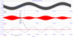
Carver's test is a similar test, only without scaling. The signal is fed simultaneously to two amplifiers, one of which is reference (reference), and the second is tested. After carefully balancing the output signals using the input attenuators, the difference between the signals is monitored. Since amplifiers introduce different distortions and have different signal propagation delays, we will also see a vector difference that can significantly exceed the difference in distortion. Both Hafler and Carver independently concluded that with vector error amplitudes of less than -60 dB (1000 times attenuation), the difference in sound between amplifiers is difficult to capture.
When simulating in a simulator, you can not only measure the vector error, but also measure all types of distortion introduced by the amplifier under test. To do this, use an ideal delay line equal to the Group Delay of the amplifier under test at the test frequency. In tests, I have shown this many times.
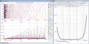
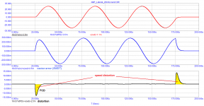
The last examples are given using a burst of three sinusoids with a frequency of 20 kHz which is passed through a low-pass filter with a cutoff frequency of 100 kHz (as in the DIM-100). Vector errors depend on Group Delay (tPD). The rate distortions at the moments of a sharp change in dV / dt also depend on tPD. We observe them at the beginning of the first period and at the end of the last.
As you can see, I give specific examples of tests for different amplifiers. These arguments support the theory of vector errors (see the book by Jiri Dostal).
they tried to fit the amplitude-phase characteristics of the input signal to the characteristics of the output signal of the amplifier under test attenuated to the level of the input signal. First, this cannot be done with the required precision. Second, this trim introduces linear distortion to the input signal. In the third, the input signal is low, so the distortion products are in the noise.
Carver's test is a similar test, only without scaling. The signal is fed simultaneously to two amplifiers, one of which is reference (reference), and the second is tested. After carefully balancing the output signals using the input attenuators, the difference between the signals is monitored. Since amplifiers introduce different distortions and have different signal propagation delays, we will also see a vector difference that can significantly exceed the difference in distortion. Both Hafler and Carver independently concluded that with vector error amplitudes of less than -60 dB (1000 times attenuation), the difference in sound between amplifiers is difficult to capture.
When simulating in a simulator, you can not only measure the vector error, but also measure all types of distortion introduced by the amplifier under test. To do this, use an ideal delay line equal to the Group Delay of the amplifier under test at the test frequency. In tests, I have shown this many times.
The last examples are given using a burst of three sinusoids with a frequency of 20 kHz which is passed through a low-pass filter with a cutoff frequency of 100 kHz (as in the DIM-100). Vector errors depend on Group Delay (tPD). The rate distortions at the moments of a sharp change in dV / dt also depend on tPD. We observe them at the beginning of the first period and at the end of the last.
As you can see, I give specific examples of tests for different amplifiers. These arguments support the theory of vector errors (see the book by Jiri Dostal).
No these arguments don’t support anything and only prove that subtracting one signal from an other signal gives the difference between both signals.
To call this Vector error, Speed error or Fantasy error is all the same when you can’t prove that this has any relevance to perceived audio by the listener, no matter what your references are trying to tell, mostly out of commercial interest.
Hans
To call this Vector error, Speed error or Fantasy error is all the same when you can’t prove that this has any relevance to perceived audio by the listener, no matter what your references are trying to tell, mostly out of commercial interest.
Hans
Developed in 1977, published 1999.
The output stage was modified in 2019.
Hafler's Tect is a comparison with a straight wire with gain, i.e. an ideal amplifier with a gain equal to that of the amplifier under test.
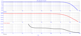
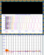
Here are the results of testing the model.
Speed distortions are measured using burst at the highest frequency of the audio range.
At medium frequencies, they are negligible.
Switching distortion is also negligible
The output stage was modified in 2019.
Hafler's Tect is a comparison with a straight wire with gain, i.e. an ideal amplifier with a gain equal to that of the amplifier under test.
Here are the results of testing the model.
Speed distortions are measured using burst at the highest frequency of the audio range.
At medium frequencies, they are negligible.
Switching distortion is also negligible
Attachments
-
 RL1999-07M_crossover-distortion.png28.6 KB · Views: 132
 -
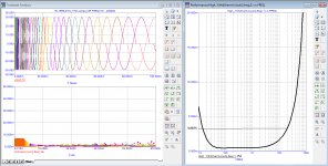 RL1999-07M_THD-vs-Freq.png77.2 KB · Views: 148
 -
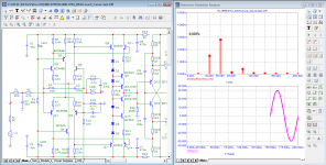 RL1999-07M_20kHz-spectr.png85.4 KB · Views: 134
 -
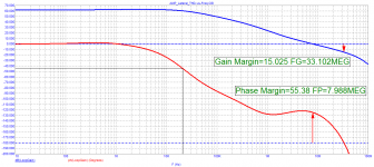
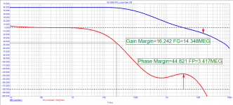 RL1999-07M_Loop-Gain.png31.8 KB · Views: 230
 -
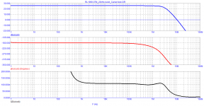 RL1999-07M_Bode.png20.8 KB · Views: 230
 -
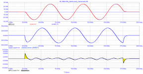 RL1999-07M_20kHz-burst_Carver-test.png27.6 KB · Views: 228
 -
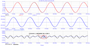 RL1999-07M_20kHz_Carver-test.png34.8 KB · Views: 244
 -
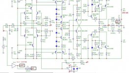 RL1999-07M_Carver-test_SCH.jpg104.4 KB · Views: 248
As usual, pictures are thrown up with no explanation of what they are, and what they are supposed to prove, but I like the pretty colors.
I probably can find an art gallery interested in exhibiting them 😎
Jan
I probably can find an art gallery interested in exhibiting them 😎
Jan
@petr_2009,
I was about to start up the simulator and spend a few hours drafting your design, but there's several now? Can you please settle on one? Also, and as Jan suggests, explain what point you're trying to make with the generated plots, without the proper context they're pretty much meaningless.
I was about to start up the simulator and spend a few hours drafting your design, but there's several now? Can you please settle on one? Also, and as Jan suggests, explain what point you're trying to make with the generated plots, without the proper context they're pretty much meaningless.
Грандиозность
He doesn't want to settle on any one single question or example... when questioned, the modus operandi tactics has been, as usual, to shift the goalpost a bit so as to avoid being picked apart by others, adding new and poorly specified information, appearing as being the brighter minded, and finally in a narcissistic fashion backstabbing and blaming others for being feeble-minded, and so it goes round and around ad absurdum.
I already asked long ago a few times if he could present a real amplifier besides the gigantic pile of simulations, but no reply until my 3rd post where he replied I do specific things... and uploaded a few oscilloscope pictures without any further explanation what those pictures means, i.e. no answer to my post.
In essence, it seems like we are dealing a with a case of Grandiosity since any normal conversation seems to not work.
Last edited:
As usual, pictures are thrown up with no explanation of what they are, and what they are supposed to prove, but I like the pretty colors.
I probably can find an art gallery interested in exhibiting them 😎
Jan
Jan,
You are so right, I almost missed it, real pieces of art, the new Banksy.
I used the beautiful internal colors to make a nice painting list and used the Banksy shredder to make it worth a fortune.
Hans
.
Attachments
Jan, for a start, imagine that I am a beginner and do not know what is the meaning of the Hafler test and try to explain to me so that I understand the essence. Then explain to me what the Bob Carver Test is.
Is there anyone here who understand the microcap graphics? help explain to those who do not understand, please!
Is there anyone here who understand the microcap graphics? help explain to those who do not understand, please!
Last edited:
@petr_2009,
No amount of discussion is going to convince anyone, so please let me know what schematic I need to simulate and what I'm looking for, so I can compare directly to another design. Please let me know the stimulus input, the desired result and what I'm looking for that sets the design you recommend apart from others. We'll get to whether that is an issue or not after we have something to compare, and discuss I might add, if anything.
No amount of discussion is going to convince anyone, so please let me know what schematic I need to simulate and what I'm looking for, so I can compare directly to another design. Please let me know the stimulus input, the desired result and what I'm looking for that sets the design you recommend apart from others. We'll get to whether that is an issue or not after we have something to compare, and discuss I might add, if anything.
- Home
- Amplifiers
- Solid State
- Musings on amp design... a thread split