I mixed two signals here just not to start from zero and stick to this thing.
The main thing is that if the signal is changing there is not just a delay.
The "simple delay" is only there after a settling time.
So what a real music signal is rather like?
It has almost continuous transients (I dont mean step signals under that) or continuous regular sine waves?
So what does this show then? What is the point you are trying to make here?
I honestly don't understand what you are trying to prove or show here.
I see a tone burst, input versus output, with a phase shift.
Jan
Attachments
I agree we are already over this debate.
You asked what "transient distortion" is (or at least how "we" mean it),
so I made these images just to show my interpretation, nothing more.
You asked what "transient distortion" is (or at least how "we" mean it),
so I made these images just to show my interpretation, nothing more.
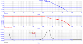
Practice shows that for low speed distortions (or, as Cortez suggests, transient distortions), the delay time should be small (as short as possible) and constant in the audio range and far beyond it. Here are the test results of two voltage amplifiers, one of which is without NFB.
The difference in the form of noise in the audio range by 40 dB (100 times) is clearly visible
The difference in the form of noise in the audio range by 40 dB (100 times) is clearly visible
Attachments

I agree we are already over this debate.
You asked what "transient distortion" is (or at least how "we" mean it),
so I made these images just to show my interpretation, nothing more.
So something with phase shift is transient distortion? Because I don't see anything else in your graph. Am I missing something?
Jan
No, you are not missing anything. Nor we wanted to reinvent anything new regarding the electronical aspect.
The whole FCD, transient distortion, GD, etc... approach wants only to emphasize the impact.
And the reason: usually it's not considered as an important issue at all.
In most designs phase shift is mainly just a number we have to deal with to make our amplifier stable.
But we believe/claim that it's much more significant. In fact one of the most important properties.
Extra: measuring the "middle section" of the signal with THD is very misleading,
although a good basic tool to measure general (non transient = continuous) distortion.
But a static single sine wave will have exactly the same phase shift. Yet we do not say that because of that, it is distorted.
Jan
Jan
That's exactly the point!
"Transforming" it to just an "innocent" AC phase delay means
it's not a distortion anymore but just an irrelevant time delay.
With a continuous sine wave it "disappears" (looks like a constant phase shft).
With non-continuous (continuously transient, random) signal it's always present.
It's "size" depends of course on the content of the signal.
Extra: in a fed back amplifier there are not just one input.
The complex load and every error that is present means a new transient as well.
All good. So what does that have to do with FCD, transient distortion, what have you? What is the problem?
BTW it is either phase shift or delay, two different things. I think here we have phase shift. The delay is just nanoseconds.
Jan
BTW it is either phase shift or delay, two different things. I think here we have phase shift. The delay is just nanoseconds.
Jan
Last edited:
There is no problem. All these terms target the same thing:
To draw attention that GD is not a thing that should be overlooked.
All these images try to visualize and express the importance of the effect of the speed.
The faster an amplifier is the smaller this kind of speed distortion is, that's all.
To draw attention that GD is not a thing that should be overlooked.
All these images try to visualize and express the importance of the effect of the speed.
The faster an amplifier is the smaller this kind of speed distortion is, that's all.
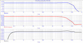
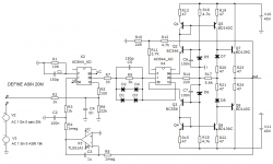
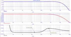
Hawksford understood perfectly well what the sound quality depended on. I think Hawksford paid a lot of attention to increasing the linearity of the amplification stages without the use of NFB for a reason. Here is one example of such voltage amplifiers. The linear section of the Time Propagation Delay stretches almost up to 1 MHz.
Attachments
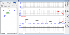
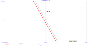
Bonsai has repeatedly emphasized that GDelay and phase shift are different concepts. With a constant GDelay, the entire signal spectrum simply shifts in time without violating the structure of the signal itself (its harmonic components, envelopes of spectral components).
Therefore, it is important for sound that the group delay is linear up to at least 200 kHz. The figure shows the phase shift of the signal with a GDelay = 100 ns in two scales: in logarithmic and linear.
Therefore, it is important for sound that the group delay is linear up to at least 200 kHz. The figure shows the phase shift of the signal with a GDelay = 100 ns in two scales: in logarithmic and linear.
Attachments
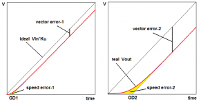
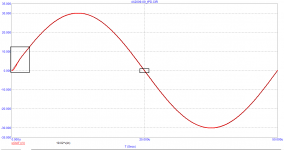
First, let me remind you what I mean by speed distortion (figure with two levels of delay)
The condition for the ideal transmission of any signal without distortion of its shape is often shown in textbooks (top graph). In this case, all harmonic components of the signal will simply be shifted in time by the same amount of time. But in real quadripoles this is impossible due to the presence of speed distortions, which was shown in his book by Jiri Dostal.
Therefore, as Cyril Hammer says, the effect of the signal propagation delay will be minimized only if the signal delay is negligible.
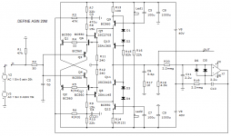
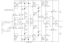
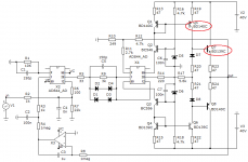
Let's go back to the above scheme: Musings on amp design... a thread split.
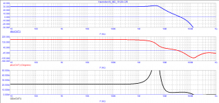
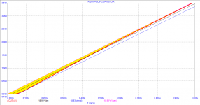
The amplifier has a negative group delay = - 23 ns in the audio range. At the same time, above 150 kHz, the GDT becomes positive and reaches almost 50 ns. Let's see how this affects speed distortion.
At the initial moment of time, the signal is delayed up to 30 ns, and only after 400 ns the signal crosses the line of the ideally transmitted signal, followed by a 23 ns lead in the steady state. The total time to reach the steady state mode is delayed for more than one microsecond - this is speed distortion. To see them in all their glory, let's delay the signal at the amplifier input by 23 ns so that the steady-state mode goes to an ideal graph, figure with index 2.
The condition for the ideal transmission of any signal without distortion of its shape is often shown in textbooks (top graph). In this case, all harmonic components of the signal will simply be shifted in time by the same amount of time. But in real quadripoles this is impossible due to the presence of speed distortions, which was shown in his book by Jiri Dostal.
Therefore, as Cyril Hammer says, the effect of the signal propagation delay will be minimized only if the signal delay is negligible.
Let's go back to the above scheme: Musings on amp design... a thread split.
The amplifier has a negative group delay = - 23 ns in the audio range. At the same time, above 150 kHz, the GDT becomes positive and reaches almost 50 ns. Let's see how this affects speed distortion.
At the initial moment of time, the signal is delayed up to 30 ns, and only after 400 ns the signal crosses the line of the ideally transmitted signal, followed by a 23 ns lead in the steady state. The total time to reach the steady state mode is delayed for more than one microsecond - this is speed distortion. To see them in all their glory, let's delay the signal at the amplifier input by 23 ns so that the steady-state mode goes to an ideal graph, figure with index 2.
Attachments

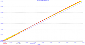
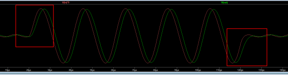
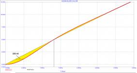
I am reproached here that I use the wrong transistor models. Replaced models with those corrected by Bob Cordell. Here is the result. Areas enclosed by a square are enlarged and shown in separate figures.
the time to reach the steady state takes about 3 μs
the time to reach the steady state takes about 3 μs
Attachments
To draw attention that GD is not a thing that should be overlooked.
All these images try to visualize and express the importance of the effect of the speed.
The faster an amplifier is the smaller this kind of speed distortion is, that's all.
We are going around in circles. Inputting a signal to the amp that has frequencies that are way out above the audio band, see that those frequency components are attenuated, then worry about that.
Why? What's the point? If I am an audio designer, what does it for me, except distracting me from making better amps?
Jan
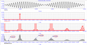
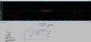
Then please recommend a (non-continuous signle sine wave that has some normal audio band transient) test signal that you accept.
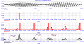
I made this sim with 5kH + 20kHz sine waves mixed with input filter 1k + 330pF.
Is this also out of the normal audio band test signal?
It shows that the difference (output error -> distortion) is the biggest when the signal speed is fastest.
I made this sim with 5kH + 20kHz sine waves mixed with input filter 1k + 330pF.
Is this also out of the normal audio band test signal?
It shows that the difference (output error -> distortion) is the biggest when the signal speed is fastest.
Attachments
There are many posts here that discuss low pas filtering an input signal.
Also, a discussion of a special signal developed for exactly the testing you want to do. DIM-30, DIM-100 signals.
Jan
Also, a discussion of a special signal developed for exactly the testing you want to do. DIM-30, DIM-100 signals.
Jan
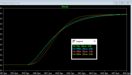
The square wave response with different delay values.
Input RC = 1k + 1nF
Attachments
- Home
- Amplifiers
- Solid State
- Musings on amp design... a thread split