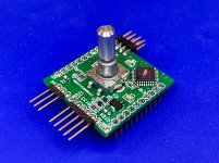
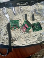
Got the remainder of the headers installed on the uController board along with the proper encoder. Added the pull-up resistors on the back. The steamship is ready to test! Just need to add some temporary input/output pigtails and some LEDs so I can see what it's doing.
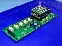
This is the single-ended set. Balanced set upcoming, but same additions.
This is the single-ended set. Balanced set upcoming, but same additions.
Attachments
Any you like with an resistor.
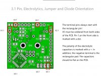
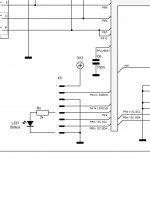
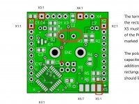
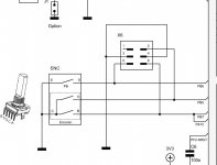
Please advise which pins on X5 to connect to, the schem is a bit unclear, anode to PA2 with resistor, is that X5.5?
I can't see where installing the LED is mentioned, not even in the BOM, only in the setup instructions. Still not sure why I needed the remote, it reads as being optional.
Please advise which pins on X5 to connect to, the schem is a bit unclear, anode to PA2 with resistor, is that X5.5?
I can't see where installing the LED is mentioned, not even in the BOM, only in the setup instructions. Still not sure why I needed the remote, it reads as being optional.
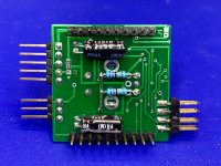
Yes, between pin 5 of x5 and ground. Pin 3 is grounded so you can use that. If I understand correctly, you have pin 1 3 5 7 on the same side. I haven’t built mine yet but I’m pretty sure that is correct.
Hubert
Attachments
Then push the encoder key and check status led toggle.
I can’t see any key
I can’t see any key
What key Daniel? You mean press the encoder? Tried everything...
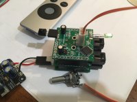
Encoder push button connections are not populated on your picture...
3 pins on one side are for encoder, 2 pins on other side are push button...
3 pins on one side are for encoder, 2 pins on other side are push button...
Last edited:
What key Daniel? You mean press the encoder? Tried everything...
I think that what Daniel mean is that the switch of your encoder is not connected.
Edit: just saw that Ripster beat me to it
Attachments

Last edited:
😀I beat you to it, but you included the photo that points to the exact location... 😀
I think that what Daniel mean is that the switch of your encoder is not connected.
Edit: just saw that Ripster beat me to it
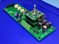
Thank guys, looks like I misunderstood again. Looking at the traces on the PCB, one of the two pins is gnd, the other is directly connected to pin 3 of the encoder pins below. So I need to bridge across pins ?
A continuity test proves it - the pins are connected.
I thought Daniel included the new row of encoder pins to accommodate a single header? it should work...
I can't make sense of it - can someone look at the traces and confirm? Attached the same pic to show
Attachments
Yes I think that you are right. You need the switch to be connected between one of those connections and ground.
Ah it's the Gnd pin that need connecting?... the other pin is only connected to pin 3, a bridge will do.
edit - sorry you beat me... 😉
edit - sorry you beat me... 😉

Yep, tried it. Nothing again. Damn. Possibly this should have a separate discussion thread, sorry to pollute the swap meet...
But - probing pin 9 (PA2) of the MCU gives 0.2mV to the LED anode, the MCU is getting 3.25V in Ok, will take a look at the datasheet but Daniel - is there any other checks around the MCU I can make?
But - probing pin 9 (PA2) of the MCU gives 0.2mV to the LED anode, the MCU is getting 3.25V in Ok, will take a look at the datasheet but Daniel - is there any other checks around the MCU I can make?
I hope this female header is more suitable for the second muses.
Yes, but 10 pins are enough😉