Yep, tried it. Nothing again. Damn. Possibly this should have a separate discussion thread, sorry to pollute the swap meet...
But - probing pin 9 (PA2) of the MCU gives 0.2mV to the LED anode, the MCU is getting 3.25V in Ok, will take a look at the datasheet but Daniel - is there any other checks around the MCU I can make?
Just to be sure, you understand that the switch is momentary? It make a brief contact between pin 5 and ground than release. What is the exact model of your encoder ?
@Ylab: Thanks for your support!
@passive420:
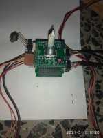
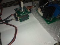
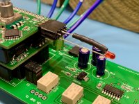
Please show pictures.
The push button is connected to PB6 and GND.
A short push toggle the mute function. The status led show the state.
@passive420:
Please show pictures.
The push button is connected to PB6 and GND.
A short push toggle the mute function. The status led show the state.
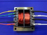
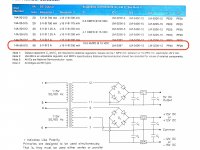
Smoked my transformer yesterday on the 18V side. I guess it was too small for this application. Boards still measure good with no shorts on any PSU components. Guess I'll invest in a better transformer. 🙂 The sample circuit in the transformer spec sheet is configured a bit differently than the way the PSU on the main board is set up, so it's possible this was a self-inflicted problem. I'm not horribly worried about it. I'll get a proper dual-wound transformer for the 18V side (+/-15V circuit). 9V side (+5V circuit) held up just fine.
Attachments

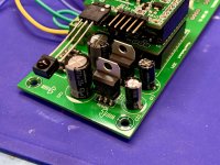

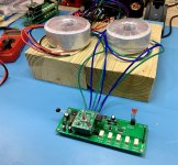
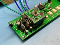
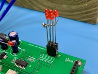
Completed and tested.
Attachments

Last edited:
Awesome ! How do you like the sound of it? Still waiting for parts to arrive. over here.
Completed and tested.
Thanks, this is a draft setup for function test only.
It isn't mine. I have built this for a friend.
I have complete it just now, no listening test yet.😉
It isn't mine. I have built this for a friend.
I have complete it just now, no listening test yet.😉
Last edited:
Troubleshooting help
Hello All,
Hoping for some troubleshooting help. I have built my 2.0 unbalanced unit including main board. Supplying +/- 15VDC from external power supply (diodes jumped) but using the onboard regulators for the 5VDC (9V transformer secondary supply).
I have assembled everything and checked for +/- 15V and 3.3V at X1 and X2 on the controller, also 3.3V at the IR receiver. All is OK.
But no light on the LED at X5. Voltage at X5 across pins 3 and 5 is 500mV.
Tried to hold the pushbutton on power up but also no light. No lights on the main board at X1 either.
Any thoughts or hints?
Best,
Mike
Hello Mike,
please double check the controller pin connections to the pcb.
Also you can measure the voltage at the push button connection (PB6).
I configured the pull up for this pin.
You have to measure 3.3V if the button is not pressed.
please double check the controller pin connections to the pcb.
Also you can measure the voltage at the push button connection (PB6).
I configured the pull up for this pin.
You have to measure 3.3V if the button is not pressed.
Hi Daniel,
I get only 900mV at pin5 on X6 (PB6)
And X5 pin1 is only 3V (not 3.3V). REG30 output is 3.3V
Reflowed the controller pins - everything looks OK
Best,
Mike
I get only 900mV at pin5 on X6 (PB6)
And X5 pin1 is only 3V (not 3.3V). REG30 output is 3.3V
Reflowed the controller pins - everything looks OK
Best,
Mike
With Mainboard 3V3 supply:
In this case controller board J2 is connected from 2=> 3?
If the controller is running you have to measure around 3V at X6 pin 5 (PB6).
Otherwise check the voltage at vdd and vss from IC10.
Daniel
In this case controller board J2 is connected from 2=> 3?
If the controller is running you have to measure around 3V at X6 pin 5 (PB6).
Otherwise check the voltage at vdd and vss from IC10.
Daniel
Yes J2 is jumped Pins 2-3
IC1 output is 2.9V against 4.5V input
I can see 2.9V everywhere except X6 Pin 5
IC1 output is 2.9V against 4.5V input
I can see 2.9V everywhere except X6 Pin 5
IC10: Vdd is 3.3V but only momentary at power up. It degrades within 30s to 2.7V and stabilizes. Vss is 0V.
To confirm I have not installed the pull-up resistors (assumed I had the latest FW version).
Best, Mike
To confirm I have not installed the pull-up resistors (assumed I had the latest FW version).
Best, Mike
Also at VDD,VSS from IC10 direct?
Yes, you have the last FW.
2,7V is high enough for the micro. But you have to search for this behavior.
Remove the Muses board, and IR receiver and check again.
2,7V is high enough for the micro. But you have to search for this behavior.
Remove the Muses board, and IR receiver and check again.
It is definitely something on the controller board. I have now replaced the entire IC1 circuit components but no change. Same with IR and encoder disconnected.
Is there anyone on this board can sell a complete assembled kit? My soldering skills are horrible.
Hi Daniel,
On the Version 1 of the VC (Muses 72320), is it possible to change he Zin (default is 20kOhms)?
Thank you!
On the Version 1 of the VC (Muses 72320), is it possible to change he Zin (default is 20kOhms)?
Thank you!
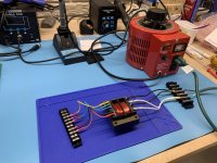
I got new transformers and got a test rig set up today. Oddly, neither the single-ended or balanced set would boot. No blinking lights or anything. Power supplies check good (+/-15VDC, +5VDC, +3.3VDC) and voltages are getting to the CPU. Encoder registers pushes and turns. Any suggestions on places to begin my search? I suppose I could separate the layers and power them individually but I don't have a power supply for that. Would have to go borrow one.
When my previous transformer shorted out, it appears to have taken down the -15V regulator, so I get to replace that as well.
Edit: As I recheck my wiring configuration, I realize there is no earth/audio ground. It's all floating, which could be an issue. Where is the appropriate grounding point for this device? When using AC, it doesn't appear there is a place to connect one.
Attachments
Last edited: