To be honest, I only bought the Ohmite because the Vishay's were out of stock. I just picked the next ones on the list that were available because I'm too impatient to wait. 🙂
MOX70031000BYE Ohmite | Mouser
Expensive little guys...
MOX70031000BYE Ohmite | Mouser
Expensive little guys...
@Chris,
no no my stupid ... I asked (only) for the black one on the MUSES board .. Ohmite, ok will take a look to them. 🙂
On my other build I will use Vishay Z-Foil .. and we will see. ;-)
Last edited:
Daniel,
I ordered my boards on April 7th and you posted the wake up issue on the 10th.
Would you know which software I have in it?
...
Thanks,
Don
All send kits before April 10th. are v1.
You can check the version by your own (see documentation).
Daniel
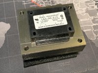
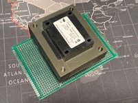
56VA 9V/36V (18V x2) transformer came in today. Should make a fine source of AC for the volume control. Might even be a good choice for some other devices. I’ll mount it to a proto board, add some Euroblocks—instant power source. Not terribly beefy boards, but should be satisfactory until I want to build something purposeful.
Part number is a few posts up.
Part number is a few posts up.
Attachments
Last edited:
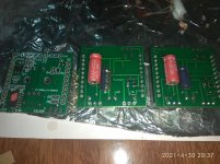
This is my progress, my friend will wait for a little. 😉
Hand made, no oven😎
Not cleaned yet..
That's impressive Thimios!
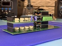
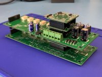
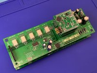
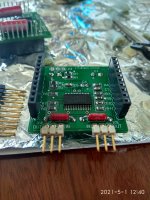
Got as far as I can today while waiting for the last couple of connectors and the rotary encoder to arrive. Got 'er packed and stacked. I had to desolder some connectors and replace them with Arduino-style stacked headers so that they could nest together.
For those familiar with this setup, you'll notice that connectors X3, X4-3, and X4-4 aren't installed. I'll be capturing the audio at a non-standard location for a special integration in my project. So I've left those connectors out of this set as I'll be wiring directly to the board(s) at these locations.
For those familiar with this setup, you'll notice that connectors X3, X4-3, and X4-4 aren't installed. I'll be capturing the audio at a non-standard location for a special integration in my project. So I've left those connectors out of this set as I'll be wiring directly to the board(s) at these locations.
Attachments
Last edited:
When the encoder is installed, I imagine it will look like a steamship 🙂
Nice work. It looks great. Has a little lego look to it.😀
Don
I believe you are correct.
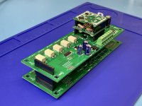
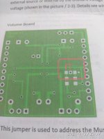
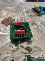
This will be used as a single-ended boards.
How must be set the jumper adress in two boards?
Same as in photo 2?
Got as far as I can today while waiting for the last couple of connectors and the rotary encoder to arrive. Got 'er packed and stacked. I had to desolder some connectors and replace them with Arduino-style stacked headers so that they could nest together.
For those familiar with this setup, you'll notice that connectors X3, X4-3, and X4-4 aren't installed. I'll be capturing the audio at a non-standard location for a special integration in my project. So I've left those connectors out of this set as I'll be wiring directly to the board(s) at these locations.
Nice, very nice Work! 🙂
Hi my friend,before i will solder headers, is this the way you prefer?
Please, let me know. 😉
Please, let me know. 😉
Attachments
Last edited:
Please can you explain a little 😕
Thanks again!
Thanks again!
Attachments
Last edited:
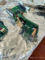
You don’t need the arduino stack headers for unbalanced.
Please have a look to the documentation pictures.
Please have a look to the documentation pictures.
I see you have two volume attenuators boards there. Are you building a 4-channel unbalanced system? If so (meldano will correct me if I’m wrong) then I believe that one set of stackable Arduino-style headers are needed on one board, and a regular female (non-stacking) header on the other. That way signal and voltage can pass to each board.Please can you explain a little 😕
Thanks again!
I’d have to double check the documents, but I believe you’re correct with your photos, presuming the above is true. If you uses stackable headers on both boards, you may just end up cutting off the long leads you don’t need on one of the boards.