After Hesener has returned to home and has instructions ready we can start the group buy. The circuit has already proven to work. Only the final trimming of the RIAA has to be decided on, so Ricardo has to finish his Paradise. He and Sampler are our RIAA precision
experts.
Hi I'm back, have checked this thread though. So far I believe it is only my Paradise up and running, or did I miss something? Maybe we should have at least one, two more PCBs up and running so we can be shure....
Yes, your one is the only one that is working. I think Ricardo will be next or he is already there but does not say. I have two pairs ready in a week or so.
Do you have the ability to measure RIAA precision, Alfred ?
Do you have the ability to measure RIAA precision, Alfred ?
Jan Didden uploaded a series of files about decoupling caps that is very extensive.
Here is Part 1.http://www.linearaudio.nl/Miscellaneous/bypass_capacitors_part1.pdf
Here is Part 1.http://www.linearaudio.nl/Miscellaneous/bypass_capacitors_part1.pdf
Here is an article by Barry Gilbert pointing out the current feedback opamps have no problem with slewing:http://www.linearaudio.nl/Documents/Are Op Amps Really Linear.pdf
Yes, your one is the only one that is working. I think Ricardo will be next or he is already there but does not say. I have two pairs ready in a week or so.
Do you have the ability to measure RIAA precision, Alfred ?
Very cool. I am listening to it right now ;-), hope you guys join me soon!
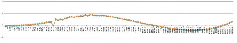
I built a inverse RIAA based on the standard Lipschitz circuit, but I am afraid it is not very precise. But as you mentioned the FPS is precise to +/- 0.1dB, so I used that as reference.
So here is the RIAA compliance of my Paradise below, normalized to the FPS' compliance. Remember I have matched the caps in both channels to each other, and the absolute value is better than 1%, and so are the resistors. Both channels were basically identical in performance, although I still haven't adjusted the current sources to remove the offset.
Attachments
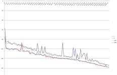
This you may find interesting as well - output noise spectrum of both phono stages.
(Please ignore all the spikes, my test setup was handsoldered in the living room, lots of noise sources around. And I also suspect my shunt regs in the FPS are MUCH worse than Frans' regulators, and the fact they are fully integrated with the preamp helps too).
The upper curves are from the FPS , the lower curves from the Paradise. It is interesting that the distance at lower frequencies is higher than at higher frequencies - could this be the 1/f noise of the JFETs?
To me this confirms my subjective assessment of the Paradise phono stage, I could hear less noise when I did the noise test Joachim suggested. It is dead quiet, and quiter than the FPS. Heck, I am thinking of using it as an LNA for noise measurements (without the RIAA, of course)...
Attachments
Last edited:
Hesener, you may have a version of the FPS that has the wrong "bass" resistors in both places
Because i originally thought that the output resistors of the servos are in parallel. The correct value is 110kOhm and you may have something like 140kOhm. This are resistors R44, R45 in the schematic that is published in Linear Audio Volume 0. To get that right simply solder 1Mohm over the 4 "bass" resistors.
The noise difference can be explained easy. The FPS has 3dB worse S/N because it is balanced. The bigger difference in the bass comes from the lower 1/F noise of the BJT´s. The FPS is very quiet so the Paradise is in exalted neighborhood.
Hesener, you may have a version of the FPS that has the wrong "bass" resistors in both places
Because i originally thought that the output resistors of the servos are in parallel. The correct value is 110kOhm and you may have something like 140kOhm. This are resistors R44, R45 in the schematic that is published in Linear Audio Volume 0. To get that right simply solder 1Mohm over the 4 "bass" resistors.
The noise difference can be explained easy. The FPS has 3dB worse S/N because it is balanced. The bigger difference in the bass comes from the lower 1/F noise of the BJT´s. The FPS is very quiet so the Paradise is in exalted neighborhood.
will try, thanks for the information!
This you may find interesting as well - output noise spectrum of both phono stages.
(Please ignore all the spikes, my test setup was handsoldered in the living room, lots of noise sources around. And I also suspect my shunt regs in the FPS are MUCH worse than Frans' regulators, and the fact they are fully integrated with the preamp helps too).
The upper curves are from the FPS , the lower curves from the Paradise. It is interesting that the distance at lower frequencies is higher than at higher frequencies - could this be the 1/f noise of the JFETs?
Naah, you can do better with JFETs in your FPS when even I got this chart from just two K170s with 3R9 under each and a single K170 second stage (bare bones zero PSRR simplistic phono). Single shunt reg and common matrix board ground for both channels. See where you got a loop or a field contamination. Goes to -110dB at 20Hz if with K369s with seriously less of 1/f ascent even. That chart is feeding from 5 Ohm source divider at 0.5mV and 0dB is 1VRMS BTW.
Attachments

Salas, the FPS stage is balanced, so there is always a 3dB penalty. On the other hand i found a way to reduce the noise in the FPS. That has to do with how i made the cascodes. It is a ground referenced common base stage that has quite a big resistor from cascode transistor base to ground. I will publish that mod in half an hour.
JG,
3dB I expect, but 15dB worse at 20Hz than basic SE and that much harmonic noise, something wrong beyond spec is going on in that build I guess.
3dB I expect, but 15dB worse at 20Hz than basic SE and that much harmonic noise, something wrong beyond spec is going on in that build I guess.
Ok, you talk about the bass. Sure, there is something wrong. The input also needs a balanced measurement signal, the Paradise not.
And the spikes in the mids. They look like having a harmonic relation. 6dB worse than 3dB VS SE higher than 1/f must be the balanced penalty plus the incompatible source signal and/or design detail you wanna fix.
That is the differential feedback path. They do not contribute to noise. They are the feedback resistors of a discrete INA that forms the input stage. ( (124 +124 ) / 2,5 ) + 1
is the gain formula. So we have ca. 40dB of differential gain. I did everything "wrong" in the FPS, including heavy feedback around the input stage.
is the gain formula. So we have ca. 40dB of differential gain. I did everything "wrong" in the FPS, including heavy feedback around the input stage.