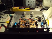
I built the 2SK369 folded cascode / OPA637 design I posted early on in this thread.
That one?
Nice build. Are the LEDS a dedicated Vref instead of the resistive voltage divider?
That one?
You're a fast searcher. Yes, that one. At least, close to it.
The LEDs bias the cascode transistors. Inspired by this here thread.
All six regulators are emitter followers. All supply currents are nominally constant, the front-end innately, the opamp too: the 637 drives its normal load and at the same time an inverting opamp with the same load, both in class A.
The supply itself is another box, in fact a commercial Michell/Trichord Never Connected with regulated +/-22V.
Hi Werner,
nice build!
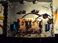
Regarding layout of the input stage: do you have seperate grounds or is the thick silver stripe at the psu input V+? If seperate, which resistor goes straight to the psu ground?
What are the golden/black boxes above the 637's? I did not understand your comment what exactly the second opamp does, do you like to elaborate?
I build both versions of your phono (on protoboards, no 'builds-to-stay') with minor variations and experimented a bit further.
I had to make the load resistor for the input fet trimmable to get the best working conditions for it. I second your comment regarding trebles. It offers a lot of resolution too, very valuable for classical music. However, my version tended to be a bit foggy on very complex material, and so far I have not found a remedy. It would be interesting if your version differs in this aspect.
Rüdiger
nice build!
Regarding layout of the input stage: do you have seperate grounds or is the thick silver stripe at the psu input V+? If seperate, which resistor goes straight to the psu ground?
What are the golden/black boxes above the 637's? I did not understand your comment what exactly the second opamp does, do you like to elaborate?
I build both versions of your phono (on protoboards, no 'builds-to-stay') with minor variations and experimented a bit further.
I had to make the load resistor for the input fet trimmable to get the best working conditions for it. I second your comment regarding trebles. It offers a lot of resolution too, very valuable for classical music. However, my version tended to be a bit foggy on very complex material, and so far I have not found a remedy. It would be interesting if your version differs in this aspect.
Rüdiger
Hi Werner ! Could you post the circuit diagram of your latest version ?
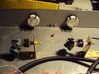
I am building a Phono Amp for Martina Schöner ( L´Art du Son, Lorycraft-Garrard ) that i call UPE ( Universal Phono Equalizer ). Martina likes to listen to pre RIAA opera, jazz and pop so she needs alternative equalization curves. My new topology: Transconductance Input Stage, Programm Module, Buffer allows that by interchanging the program module.
It also allows to bypath the EQ totally and then the UPE is a Pre-Pre ( Headamp ).
Here are some photos of the prototype. More explanations will come.
Attachments
Sorry, I don't have a complete circuit diagram.
do you have seperate grounds
Yes. No naughty currents are mixed up with the nice ones.
What are the golden/black boxes above the 637's?
NOS styroflex caps.
I did not understand your comment what exactly the second opamp does, do you like to elaborate?
An inverting amplifier (TL071) hangs off the output of the OPA637. It is so configured that, for a given load impedance (my ADC), it pulls a current from the supplies that is the inverse of the 637's current. So the net supply current is zero.
I had to make the load resistor for the input fet trimmable to get the best working conditions for it.
I have a second identical board, with sockets everywhere. Prior to building the thing I characterised all my 2sk369s, bipolars, and bias LEDs, in circuits similar/the same as in the actual preamp. Not easy, as the front-end is, let's say, thermally full of temperament ...
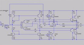
The Transconductance-Transimpedance stages i am working on get more and more gain by raising the output impedance of the current mirrors. The cascoded current mirrors i have shown here are only a beginning. You can imagine that DC offset gets a real problem when you feed the output current into a high impedance network like an RIAA shaper. As a consequence i am looking together with another engineer at novel ways of DC management without the use of Servos or big coupling caps. In fact we got a prototype working. What we need is a high speed buffer with very low input capacitance, exactly a gain of one and ideally zero output impedance plus low intrinsic self DC output. This can be made near perfectly with a good OP amp used as voltage follower and that is what we use in the prototype. Somehow this was too easy and the better i get at designing discrete circuits the more uncomfortable it feels to go the easy road by restoring to Op amps. Unfortunately my usual Fet-Darlington buffer that was based on a JLH design is not good enough for that task. It sounds very well but it has still some input capacitance, an non zero output impedance because of the presence of resistors in the collector chain and as a consequence a gain of less then one.
So i redesigned it. First i cascoded the input Fet´s. I use the Hawksford cascode here, a rare sight and i have never seen it being used in a buffer. It feeds back the base current of the cascode transistors into a low impedance joint of the amplification chain and gives an improvement in speed and distortion at the expense of some gain. Gain i have a lot in my design so i thought it could be beneficial here. The second change is putting the resistors into the emitter feed of the output darlingtons and not into the collector feed. This way i make a kind of "Super Szikley". This whole "thing" is theoretically damn fast and the old buffer with a -3dB point of 16MHz suddenly seems old and tired. How much of this speed i can rescue into a stable circuit has to be seen because Szikleys are famous for oscilation. Of cause i have and idea how to fix it when it ocures, so let´s wait for tomorrow when i put this circuit through it´s paces.
So i redesigned it. First i cascoded the input Fet´s. I use the Hawksford cascode here, a rare sight and i have never seen it being used in a buffer. It feeds back the base current of the cascode transistors into a low impedance joint of the amplification chain and gives an improvement in speed and distortion at the expense of some gain. Gain i have a lot in my design so i thought it could be beneficial here. The second change is putting the resistors into the emitter feed of the output darlingtons and not into the collector feed. This way i make a kind of "Super Szikley". This whole "thing" is theoretically damn fast and the old buffer with a -3dB point of 16MHz suddenly seems old and tired. How much of this speed i can rescue into a stable circuit has to be seen because Szikleys are famous for oscilation. Of cause i have and idea how to fix it when it ocures, so let´s wait for tomorrow when i put this circuit through it´s paces.
Attachments
Hello Joachim,
The buffer stage looks similar to the 8 Watt Hiraga design, of course no output Transistors and you are using the Darlingtons and not a driver stage. Cool!
For the FF2010 Linestage I received several high quality PSU from a fellow DIY'er to test the sound influence of the psu.
Regards
SAm
The buffer stage looks similar to the 8 Watt Hiraga design, of course no output Transistors and you are using the Darlingtons and not a driver stage. Cool!
For the FF2010 Linestage I received several high quality PSU from a fellow DIY'er to test the sound influence of the psu.
Regards
SAm
Joachim,
here is my all-out buffer stage. You don't need the servo if you don't have DC at the input. It's rock stable if build properly, DC and AC wise. Normally, R7 can be omitted. You can make it tending against zero output impedance if you enclose it in a loop with a gain stage, and use beefier out put Q's.
A tad complex, maybe 🙄
Rüdiger
Attachments
Hi Sam ! You are right, the Le Monstre looks very similiar. I was not aware of that. Of cause my stage does not have voltage gain and has the Hawksford cascode. By the way i build the first original Le Monstre in Germany for Kurt Hecker in 1983. A friend of mine bought it some years ago from a customer that had disasambled it. It was in terible shape but my friend is a very good craftsmen and he has restored it perfectly. It playes again perfectly well and it is only 5km away from my house, so somehow it came back to Papa. I will make a photo and post it.
Rüdiger, your buffer looks good and i think it is not that complicated when you boil it down without the "helper" transistors. I really like the way you implemented the servo.
Filtered with capacitance multipliers and working on the current mirror the sonic impact of it should be minimal.
Today i will finish my buffer and look if it is stable.
Sam, your experiment with PSU´s is important. As i have said several times here, i am not good at designing PSU´s. I rather try to make my circuits imune to PSU issus as good as i can. Nevertheless your shootout could spearhead the path i should follow ones you found the best sounding solution. I will then try to learn why that particular topology works best and then we have another thread about PSUs for Audio.
I still have not build the Meaner Shunts that Salas has deshned for me, but i have now all the parts i need and i asume i can make it work in the next two weeks.
I still have not build the Meaner Shunts that Salas has deshned for me, but i have now all the parts i need and i asume i can make it work in the next two weeks.
Yes, it´s a great way to do it. Send me your e-mail adress by PM and i show you something that could interest you.
On Holger Barskes Website is a small listening test of my Nobrainer Phonostage. What i found is that a typical DIY´s likes simple circuits. Look at the success that Salas has for example. So i thought the Nobrainer is ideal for DIY, even for beginners. On Holgers site are also comments about my stage and one guy shows a circuit from a Japanese designer that uses the NE5534 for MC duty. I think this is not such a good idea and when i expressed my doupth a small discussion stated about the merits of the NE5534. I know that OPamp very well. The first design i made in 1983 with the NE5534 was a preamp. At that time the NE5534 was revolutionary. It was the first OP i really liked.
It has some problems with common mode distortion and offset. Voltage noise is 3.5nVqHz and current noise is quite low for a bipolar so it is low noise with MM cartridges. For MC it is too noisy but still some companies like LFD use it in more affordble stages. Common mode distortion can be avoided by using shunt feedback and voltage noise can be reduced with massive paralleling. I thought when a caveman can build an amplifier then a German Neanderthal man can build a phonstage so i designed a stage that should work and is extremely simple. I use 8 NE5534A in parallel with a one stage shunt feedback RIAA. Gain of that stage with a Titan i that has 6 Ohm impedance including cable loss is 60dB. Gain at 20kHz is around 40dB with RIAA and the NE5534 has a gain of 5000 @ 20kHz leaving a feedback factor of 34dB @ 20kHz. This is not much for an Opamp but still i think it is sufficient. This is not a state of the art Phonostage in any way but everybody has some NE5534 around or can buy them for less the 50 cents a piece. This stage can be build for less then 20 € if a semy decent PSU is available. The NE has good PSU rejection and even a simple Pi filter or some batteries buffered with elcaps of say 2000 uF will do. I thouht about how i will call it and no, i do not call it the Neanderthalman but it will be known as the Phonoman.
P.S. noise of that circuit is around 1.3nVqHz and offset shuld be low with a low impedance cart like mine. The plus and minus input is at near zero potential in that design and when you use a cart like the DL130 with 40 Ohm the resistors in the RIAA have to be increased by a factor of 40/6 and the values of the caps lowered with the same factor. 320 Ohm resistors have now to be fiited from Pin2 to ground in each Opamp to balance the offset voltage. Maybe i will ad a coupling cap at the output for savety.
Attachments
I build the Phonoman and got it working after some small difficulties at the beginning.
My last post has shown a DC coupled version and with the NE5534A it does not work that way. I measured around 28mV to cartridge in both channels ones i connected a 5 ohm dummy resistor. That made the output jump to over 10V with a +-12V supply. I knew that the NE5534 is not famous for low offset voltage and the OP27 is much better in that regard becuse it has a bias cancelation circuit. Still i think even the OP27 is not good enough for DC coupling at the input. Bias cancelation also brings a new source of noise. That is the reason Douglas Self does not like the OP27 or the LT1115 or LT1028.
I can not see that noise in the spec sheet so i have mixed feelings if Self is right. Comparing the AD797 he likes to the LT1028 i can not hear much difference in noise. Quite the contrary because the LT1028 seems to be well to spec all the time whereas i have some samples of the AD797, say one in twenty that have to be sorted out when you use them at the input of an MC phonostage. I solved the issue by simply inserting a 10.000uF 6.3V Pannasonic FM i keep handy for that pupose. Just to feel better i bypassed with a 1uF Wima MKT and a 10nF Rifa SSM. Actually i think the cap does more good then evil at that place. All DC coupled Phonoclone like stages i see here send considerable DC into the cartridge. After a hot debate on this thread if this is audible i build a transimpedance input stage some time ago where i could adjust the DC
at will. I found that 100uV is just audibe in my system and non of the phonoclones i see here match that criterion. If you are concerned about the distotion that this cap brings i can asure you that it is very little. An elcap develops distortion ones a high voltage develops over it. That happns in the bass in poweramps but not at the mV levels we talk about here. Burkhard Vogel had the same problem and in his typical rationate way developped a circuit where he could listen to Elcaps in the chain at the levels that are involved over headphones. He could not hear a difference with the cap in or out.
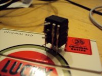
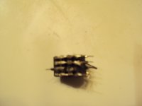
I do not know how good Burkhards ears are but i will publish that circuit tomorrow and you can make your own test. the second chage i made is that i used only 4 stacked NEs because i am soldering them directly over each other and when the circuit does not work i loose 16 chips that are hard to desolder. That buys me a worcening of Signal-Noise of 3dB and i thought i can live with that. Actually the circuit is still some 5dB better then a single OP27 that i see here in very alaborated phonos. It surprises me that stil at the noise level of the OP27 the users are extremely happy and pleased with the result. I can only asume that they listen at much lower volume then me on speakers with under 90dB efficiency. On the other hand "When the stone hits the plastic" as our chief moderator Salas whould say a hunt for extremely low levels of noise is rather academic. Well, i enyoy the spooky silence that my new Transconductance stages have the the Phonoman AC as i will call it with a stack of 4 is no match when i cranc the volume full. The noise is not particular agressive because the shuntfeedback RIAA nicely shapes it but there is a culmination of noise audible, i whould say i the upper midrange just under the presence region so it does not sound forward but slightly back. Its hard to describe but it does not go on the nerves like flicker or popcorn noise does. It´s like the sound that the wind makes when Boris Becker plays tennis ( was i the one that wrote this down ? ). At my normal listening level it is well surpressed and just audible, faintly in the backround from the midle of the speakers. That is much better performane then a 20€ stgae like that has any right too.Well i have not counted the time it needs to make it but i whould say, the next time i build it, i need 2 hours max. So how does it sound ? The first think that was obvious and i knew that from the discrete INA where i use stackes of NEs in shunt feedback is that typical robust bass. I had to turn down my sub a bit after i switched from the lates Transconductance stage. Wel actually i got a lot of noise in the beginning on one channel. After substituting the 4 Nes everything was fine so i thought they, or one of them was faulty. Actually i had taken the NEs from the considarable waiste that was left over from the development of the Discrete INA so that was a logical explanation.
I was wrong. I had forgotten to solder one row of contact but i found that out much later until i looked again at the object to photograph it. See the atatchement.
In the midrange i whould say it sounded unspectacular and neutral. I can live with that because most cheep stages do not get the midrange right at all so particular clasical music can sound dreadfull. Strangly agressive and foggy the same time. Not in this case but also not extremely tansparent. If this is good or bad depends on your system also because the Phonoman AC has a particular way to treat the treble. I have seen numorous times that the NE series of Opamps gets acused for agressive and sterile treble that borders on the edgy. Nothing could be further from the truth in this particular application. The treble is silky smooth with a tendency of rounding and a rose tinted brownish tan. If this is the consequence of the topology or my use of components that have been soldered on and from one row down of my collection i can not say.
Actually i do not have really bad components so you can find some used antimagnetic Dales, two very expensive Welvyn Metalfim, Reichelt Styroflex, Rifa PPS and COG ceramics. The elcaps are Pannasonic FM and Sprague blue so nothing here that could explain what i hear this time. I have used the same components numorous times in circuits that sounded different. Maybe i have to wait until tomorrow and listen more.
The elcas may still be a little leaky and need some forming. That can need days or weeks. Next time i will preform at least the input cap for 24 Hours.
A real fun project that was. Making something out of nothing reminds me on the times i was a teenager and we had no money but wanted to hear music well. That brought me into this game and that is the reason i love DIY.
My last post has shown a DC coupled version and with the NE5534A it does not work that way. I measured around 28mV to cartridge in both channels ones i connected a 5 ohm dummy resistor. That made the output jump to over 10V with a +-12V supply. I knew that the NE5534 is not famous for low offset voltage and the OP27 is much better in that regard becuse it has a bias cancelation circuit. Still i think even the OP27 is not good enough for DC coupling at the input. Bias cancelation also brings a new source of noise. That is the reason Douglas Self does not like the OP27 or the LT1115 or LT1028.
I can not see that noise in the spec sheet so i have mixed feelings if Self is right. Comparing the AD797 he likes to the LT1028 i can not hear much difference in noise. Quite the contrary because the LT1028 seems to be well to spec all the time whereas i have some samples of the AD797, say one in twenty that have to be sorted out when you use them at the input of an MC phonostage. I solved the issue by simply inserting a 10.000uF 6.3V Pannasonic FM i keep handy for that pupose. Just to feel better i bypassed with a 1uF Wima MKT and a 10nF Rifa SSM. Actually i think the cap does more good then evil at that place. All DC coupled Phonoclone like stages i see here send considerable DC into the cartridge. After a hot debate on this thread if this is audible i build a transimpedance input stage some time ago where i could adjust the DC
at will. I found that 100uV is just audibe in my system and non of the phonoclones i see here match that criterion. If you are concerned about the distotion that this cap brings i can asure you that it is very little. An elcap develops distortion ones a high voltage develops over it. That happns in the bass in poweramps but not at the mV levels we talk about here. Burkhard Vogel had the same problem and in his typical rationate way developped a circuit where he could listen to Elcaps in the chain at the levels that are involved over headphones. He could not hear a difference with the cap in or out.
I do not know how good Burkhards ears are but i will publish that circuit tomorrow and you can make your own test. the second chage i made is that i used only 4 stacked NEs because i am soldering them directly over each other and when the circuit does not work i loose 16 chips that are hard to desolder. That buys me a worcening of Signal-Noise of 3dB and i thought i can live with that. Actually the circuit is still some 5dB better then a single OP27 that i see here in very alaborated phonos. It surprises me that stil at the noise level of the OP27 the users are extremely happy and pleased with the result. I can only asume that they listen at much lower volume then me on speakers with under 90dB efficiency. On the other hand "When the stone hits the plastic" as our chief moderator Salas whould say a hunt for extremely low levels of noise is rather academic. Well, i enyoy the spooky silence that my new Transconductance stages have the the Phonoman AC as i will call it with a stack of 4 is no match when i cranc the volume full. The noise is not particular agressive because the shuntfeedback RIAA nicely shapes it but there is a culmination of noise audible, i whould say i the upper midrange just under the presence region so it does not sound forward but slightly back. Its hard to describe but it does not go on the nerves like flicker or popcorn noise does. It´s like the sound that the wind makes when Boris Becker plays tennis ( was i the one that wrote this down ? ). At my normal listening level it is well surpressed and just audible, faintly in the backround from the midle of the speakers. That is much better performane then a 20€ stgae like that has any right too.Well i have not counted the time it needs to make it but i whould say, the next time i build it, i need 2 hours max. So how does it sound ? The first think that was obvious and i knew that from the discrete INA where i use stackes of NEs in shunt feedback is that typical robust bass. I had to turn down my sub a bit after i switched from the lates Transconductance stage. Wel actually i got a lot of noise in the beginning on one channel. After substituting the 4 Nes everything was fine so i thought they, or one of them was faulty. Actually i had taken the NEs from the considarable waiste that was left over from the development of the Discrete INA so that was a logical explanation.
I was wrong. I had forgotten to solder one row of contact but i found that out much later until i looked again at the object to photograph it. See the atatchement.
In the midrange i whould say it sounded unspectacular and neutral. I can live with that because most cheep stages do not get the midrange right at all so particular clasical music can sound dreadfull. Strangly agressive and foggy the same time. Not in this case but also not extremely tansparent. If this is good or bad depends on your system also because the Phonoman AC has a particular way to treat the treble. I have seen numorous times that the NE series of Opamps gets acused for agressive and sterile treble that borders on the edgy. Nothing could be further from the truth in this particular application. The treble is silky smooth with a tendency of rounding and a rose tinted brownish tan. If this is the consequence of the topology or my use of components that have been soldered on and from one row down of my collection i can not say.
Actually i do not have really bad components so you can find some used antimagnetic Dales, two very expensive Welvyn Metalfim, Reichelt Styroflex, Rifa PPS and COG ceramics. The elcaps are Pannasonic FM and Sprague blue so nothing here that could explain what i hear this time. I have used the same components numorous times in circuits that sounded different. Maybe i have to wait until tomorrow and listen more.
The elcas may still be a little leaky and need some forming. That can need days or weeks. Next time i will preform at least the input cap for 24 Hours.
A real fun project that was. Making something out of nothing reminds me on the times i was a teenager and we had no money but wanted to hear music well. That brought me into this game and that is the reason i love DIY.
Attachments
Thanks, tomorrow i post the "cap listener" and i am working on a transformer coupled, inductive RIAA with 4 Josi Opamps. An expensive beast, so to say the total opposite of the Phonoman. A friend of mine has an original Audio Note IO with 1Ohm impedance and only 0.025mV output and then it gets tough, even for my best electronic stages. I already have some nice Lundahls and the good coils that Brian Sowter made me in house. I wait for Sigurd Ruschkovski to finish the tests on the Josi and then i try an all out asault.
Will use your meaner shunts this time, i promiss.
Will use your meaner shunts this time, i promiss.
I build both versions of your phono
...
I had to make the load resistor for the input fet trimmable to get the best working conditions for it.
Which versions exactly?
I have been working on and off on a seriously big version of a similar phonostage. It would be two full-width chassis, with LC regulation, pretty high voltages for the front-end etc.
But there wasn't much progress towards a commercial-grade build of this, and I wanted something to listen to quickly. Further, we were buying a house for renovation (more work!), so I decided to make a tiny version of the circuit in the few months left to me before I would re-invent myself as carpenter/mason/... So this brought some constraints:
-PCB 100x160 mm max
-only one 2SK369 per channel (don't want to deplete the stock!)
-100nF cap for 75us (wanted to use either MKV or MCap)
-approx. 9nF cap for the rest
-60dB gain
-18V supply for the front-end
-accuracy better than +/-0.1dB
This ended up being like a Chinese puzzle. I succeeded, but only with some effort and a lot of pre-characterisation of active element and measurements on partial and full circuits.
Now back to calculating heat losses and isolation layer thicknesses...
Hello Joachim.
How much gain does your schematic in post 1488 have?,
Also, does the gain come from the cascode transistors, or do the current mirrors provide additional gain?
Thanks🙂
How much gain does your schematic in post 1488 have?,
Also, does the gain come from the cascode transistors, or do the current mirrors provide additional gain?
Thanks🙂
The innitial gain of the input stage is defined at 2 x Gm x RL. RL is the output impedance of the cascoded current mirror. The cascoding raises the output impedance of the mirror
by the beta of the cascode transistors. In the case of the BC550C-BC560C beta ( or hfe )
is ca.500. The factor of 2 in the formular comes from the fact that the gain in a parallel symmetrical stage is double then the gain in a single ended stage. So you see, the mirrors do not add gain but raise the gain in the input stage by raising RL. Actually the bipolar cascodes shield the Fets so the gain comes from the bipolar cascode transistors. In that case the gain equation is (( beta x RL ) : ( Rbe + Rbv )) x 2. RL is the output impedance of the uncascoded mirror times the beta of the cascode transistor If we asume that the output impedance of the uncascoded mirror is 1kOhm then RL is 1000 x 500 = 500.000 Ohm. Rbv is zero in case of that circuit because i shunt the base current AC wise to ground with a capacitor. Rbe is ca. 35 Ohm with the cascode transistors i am using so we get 500.000 : 17,5 = 31.847. Bandwidth of the input stage is 1Mhz -3dB so gain-bandwidth product is 1M x 31.847 = 30GHz. Now you know what a beast that is.
Well i think 30Ghz is rather optimistic because i did not take stray effects into account but still in praxis we end up in the several GHz range. That gain now is shaped by the RIAA filter to ground. I have to calculate the input impedance of that filter at 1Kz and then you have to total gain of 500.000 : Ohm @ 1kHz.