I tryed the LC Audio Low Noise Supply and the Twisted Pear Placid. Both work fine.
I use 27mH coils behind the LC Audio but this is not absolutely neccesary.
You can use between 12 to 15 V. I always try my prototyps with 2 x 12V lead acid batteries.
I use 27mH coils behind the LC Audio but this is not absolutely neccesary.
You can use between 12 to 15 V. I always try my prototyps with 2 x 12V lead acid batteries.
Here is another example of a Transimpedance RIAA Stage. This time it is a common base stage with input offset cancelation. Noise impedance is around 17 Ohm when the current in the input transistors is set to ca. 3.5mA. You can double or quadruple the input transistors for even lower noise. You have to raise the iddle current by a factor of two or four in the input stage when you do that.
I like that stage and will build it.
I like that stage and will build it.
Attachments
Some cartridges really need a transformer because the output is so low that even the best active solutions have too much noise. For example the original Audio Note IO Ltd. with 0,04mV @5cm/s. The new Kondo IO-M has some more output with 0.12mV but still it is a challenge for active MC stages. Some time ago i presented a Zero Field ballanced input that was not fully worked out. After discussing with Holger Barske i made a unbalanced version with inductive RIAA. This stage is hard to beat in noise rejection and puts even 0.3nV/qHz stages to shame due to the extremely low DC input impedance of 0.75 Ohm. I talked to Lundahl and Sowter and they can make me transformers to spec. I now have the choice between MU-Metal, Nickel and Amorphous core. I do not know yet what to take. The Zero Field technology cancels the effect of the secondary winding and extents the response of the transformer to nearly DC and cancels distortion.
P.S. : I build the Common Base Transimpedance RIAA and it works.
P.S. : I build the Common Base Transimpedance RIAA and it works.
Attachments
Several people are now building my USAIG phonostage so i fell responsible to extract the best posible sound from that circuit. I gave one stage to Frank Schöder and he gave the following commend: Sounds very clean but could have a little more deep bass, noise is a little high for low output MC, should have a switchable Neumann pole.
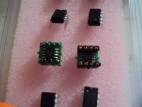
So this is what i did: I substituted the LME49720 with two single LME49990 on an adapter made by Stefan Horwege for me. The LME49990 is much more quiet with MC, has lower distortion, higher bandwidth and better PSU rejection. I prefer it over the AD797 or LT1028 i used before. I recalculated the RIAA and put an RC filter at the output that makes the RIAA curve flat over 20kHz. The old values gave the following time constants : 75.2 usec ( 0.3% off ), 291.8 usec ( 8% off ), 3000 usec ( 5% off ), that does not sound as bad as it looks because it gives only a small lift ( ca. 0.5dB ) in the fundamental tone area. The new values give : 75.2 usec ( 0.3% ) , 306,6 usec ( 3.5% ), 3200 usec ( 1% ). It is no problem to get the 75 usec and 3180 usec time constants but the 318 usec is much harder with standart values. Considering that i do not use exotic values i am satisfied with the result. I raised the 2200uF elcap to ground to 4700uF plus a 2.2uF foils cap for lower distortion and more extention in the deep bass. The Neumann Pole was added. It is switchable.
Circuit diagram with commend, picture of LME49990 adapter and a photo of a deluxe version of the USAIG 2.0 is added.
Attachments
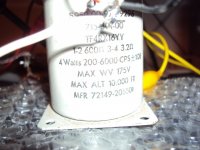
My first experiment with Zero Field technology was successfull after some playing around with values. As transformer i used a 600 Ohm - 3.2 Ohm transformer that a friend of mine bought at a Ham Fest. It must have been used for talkback to transform 600 Ohm to a little loudspeaker. The specs say 200 Hz to 6kHz +-1dB. I use it "up side down", so i use the secondary as primary and the primary as secondary. That way, the primary DC impedance is around 0.15 Ohm and the secondary is 27 Ohm. You can imagine that this gives a really worst case szenario because this transformer has very little "primary" inductance so without the Zero Field trick it gave vitually no bass. I have a little hum problem but otherwise the sound with Zero Fied was surprisingly good with decent bass and treble extension so i am really looking forward to use this technology with a better transformer. I use a cap in series with the transformer to avoid DC through the coils. In fact it was not that bad. One channel measured 27mV, the other 3.5mV so the "bad" channel gave 1mA through the transformer. This is not much and i could jumper the cap but i have not tryed that.
Theoretically i can use now a very small transformer and the OPamp compensates for any low frequency distortion. Let´s see how this develops.
Theoretically i can use now a very small transformer and the OPamp compensates for any low frequency distortion. Let´s see how this develops.
Attachments
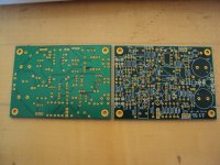
Today the PCB boards of the JOSI discrete OPamp arived. The JG Trio ( me, Sigurd Ruschkovski and Jan Didden ) has worked silently on perfecting the design. It is now version 2.81 Rev.2 so a lot of hard work was put into it. I came up with the fundamental design, Sigurd simulated and optimised the circuit and choose most of the active and passive components and Jan did the layout and the servo design.
We got the following performance : GBproduct 40MHz, Open Loop Bandwidth 40kHz, Voltage noise 1.5nV/qHz, Open Loop Distortion up to 100kHz 0.01%, Supply Voltage +-15V to +-24V, Max Bias Current in the output stage 70mA.
The circuit can put out more then 3W in Class A in theory. To make that posible the board is quite big ( 60mm x 83mm) and we use strong and fast Sanyo video transitors at the output that can be bolted to a heat sink.
This is the first PCB i hold in my hand since i started this thread, so it needed over one year to get something finalised. In fact the first circuit i designed that got a PCB was my discrete INA. It will be available from Pilgham Audio but so far i have only seen a picture and the artwork. In fact several people are working on PCB boards for my designs. I keep you posted if there is any news.
In use the Josi is very flexible. It can do what an integrated OPamp can too but also much more. A phonostage could be made for medium output MC´s and it can also be used for MM work because the double input Fet does not only have low voltage noise but also low current noise. This could be nice for the top Grados.
A headphone amp can be build, so does a line stage or a line buffer. An INA can be made from 3 JOSIs. Active filters and equalizers come to mind too.
Attachments
I slept well, thank you very much.
I put more thought into the BJT INA.
The current sourced caskode did not work so well with BJT´s so i simplified a bit.
They are now fed by a capacitance multiplier and the feedback goes directly from the collectors.
Circuits like that proved to work in designs by Douglas Self and Burkhard Vogel but they used them unbalanced.
Idle current in my design is adjutable for minimum DC offset and optimisation for an MC with higher impedance like the Denons and Clearaudios.
When i use 4 x 4 input transistors and reduce the feedback resistor to 1 Ohm i could get 0.3nV/qHz in a balanced design.
Hi,
I have few questions regarding this BJT schematic posted here few month back.
Please correct me if I am wrong, but it seems that the cartridge will see approximately 1.5V DC. Either that or (in case of 0 Ohm cartridge) 1.5 VDC has to be applied across R1 with resulting current of 600mA. The latter seems is not going to happen because of the servo opamps keeping the output voltage of the OP1 and OP2 close to 0VDC. As a result T1-T4 will be turned off.
Hopefully I am wrong and missed something else here.
Another question - is it possible to convert this schematic into single-ended similar to shown in post # 814 in "Intrumentation Headamp Unbalanced.TSC - TINA.pdf" file.
Thanks
It looks like the system did not include the attached schematic. I was referring to the schematic in the post 1022.
Yes, you are right, the schematic from post 1022 needs input caps. This input stage can be converted into single ended. I will post a circuit later this day that should work.
This circuit is straight out of Burkhard Vogels book "The Sound of Silence". I only changed the OPamps to more modern and better performing types. It should fullfill your request.
It is a single ended, all in one go MC RIAA, itself an elaboration on the well know D.Self design from the 90th. You can use other BJTs at the input and i have given many choices here earlier. I noverdays design parallel symmetric BJT transimpedance circuits with DC offset cancelation or paralel symmetric FET transconductance circuits because they can be DC coupled to the cartridge, have cancelation of second harmonic and a 3dB noise advantage.
It is a single ended, all in one go MC RIAA, itself an elaboration on the well know D.Self design from the 90th. You can use other BJTs at the input and i have given many choices here earlier. I noverdays design parallel symmetric BJT transimpedance circuits with DC offset cancelation or paralel symmetric FET transconductance circuits because they can be DC coupled to the cartridge, have cancelation of second harmonic and a 3dB noise advantage.
Attachments
Sorry, there is a mistake. R14 ( 10kOhm) and the RIAA should go to PIN3 ( +In) of the output Opamp.
Joachim,
I was more hopeful to see a symmetrical NPN/PNP BJT preamp with single ended (unbalanced) input like in post #814. My guess the one in post 814 will not work as it is.
I understand the main issue is the biasing of NPN/PNP pair which should be done in a way similar to Essex preamp.
Anyway, thanks.
Jason
You, are right, the circuits in post 814 where experimental and do not work the way i have drawn them. i do that sometimes to provoke reactions but i should not do that any more. Some people here are really serious about mistakes i make and i can understand that.
Here is a circuit you could like. It is a transimpedance circuit and has DC offset cancelation. It is extremely simple but performs very well. I was at a very influential German magazine and it compared well in sound to stages that cost 10.000,-€.
If you do not beleave me read Holger Barskes mini review on his website.
Attachments
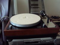
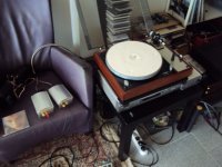
I have not listened to a good MM cartridge in ages. The last time was one of the big Grados at Wittmann in Stuttgart in an unfamiliar system. Because a friend of mine undusted his Thorenz TD160 i had the chance to mount the top Clearaudio MM, Maestro Wood. It was not easy to adjust correctly because the Maestro has tapped holes and the Thorenz arm has another mounting scheme. I used small diameter screws to circumvent the problem. The sound i got with the Inductive RIAA was a surprise. A lot has happened in MM design it seems. It had more dynamics and resolution then i hoped for but still there was this imposible to describe homogenious sound that a good MM makes. This Clearaudio is certainly the best of it´s type i heard. One problem remains.
The motor of the Thorenz made a clicking noise that was also audible thruw the loadspeakers at low level. It is the typical cogging problem that older Thorenz have so i have to repair that. Otherwise the sound was very musical and entertaining. As linestage i used my Velleman 8020 that i had rebuild to an Aikido Buffer with very good success.
The motor of the Thorenz made a clicking noise that was also audible thruw the loadspeakers at low level. It is the typical cogging problem that older Thorenz have so i have to repair that. Otherwise the sound was very musical and entertaining. As linestage i used my Velleman 8020 that i had rebuild to an Aikido Buffer with very good success.
Attachments
During the course of this thread i reported about the difficulty to get the input DC offset to zero in a common base transimpedance ( or transresistance, i think this is the correct term ) circuit. Interestingly the first circuit i posted did not have that problem because it is ballanced. The problem comes because Ube is different in NPN and PNP bipolars at the same idle current and because the cartridge is connected to the emitters is seas the difference voltage to ground. Ube is a very weak function of idle current so even biasing the input transistors grossly different does not help much. Later i found several solutions, one is a floating supply like in the Rosi and one is a voltage divider from the bases to the emitters like in the Nobrainer stage. It ocured to me some time ago that there is another more elegant option if emitter resistors are present. I developed several versions and i show you now one of them. Emitter resistors have the disadvantage of some voltage noise added but you can make them quite small or take several transistors in parallel. The advantage of emitter resistors is that they provide some linearising current feedback that also lowers tolerances in the transistors so paralleling is easy without matching. You may now ask why i always come back to transresistance circuits when the problem can be solved with Fets to do a transconductance circuit. Well, it is that dramatic and dynamic sound that circuits like that can give provided the cartridge fits. The other advantage is that they can be used as I/U converters in DA converters. Yes, most of the circuits here i presented can be used in the analog stage of DA converters. The problems are nearly the same.
So here is the circuit. The potmeter can adjust the DC input offset to zero and can be substituted with a servo. The cascoded current mirrors give enormous gain so an All In One Go Phonostage is posible too. Second i show a circuit elaboration that already works on my bench. It is a BJT-FET cascode. I am shooting thruw the eye so to say. The task now is to find N and P channel Fets that have a high enough Gate-Source voltage at the desired current and do not add noise.
So here is the circuit. The potmeter can adjust the DC input offset to zero and can be substituted with a servo. The cascoded current mirrors give enormous gain so an All In One Go Phonostage is posible too. Second i show a circuit elaboration that already works on my bench. It is a BJT-FET cascode. I am shooting thruw the eye so to say. The task now is to find N and P channel Fets that have a high enough Gate-Source voltage at the desired current and do not add noise.
Attachments
Studying the datasheet, forward transfer admittance is given as 4mS so noise can be calculated indirectly. I asume that they have a low 1/F frequency because they have been
designed for audio. Two of them seems to be just right.
designed for audio. Two of them seems to be just right.
JG-Self Linestage
A fellow DIYer has put the JG Self linestage on a PCB so this is one more circuit i posted here that can now be build easily. Actually it is a modular system with a mother board, two line boards, the stereo-mono switch and the potmeter.
A fellow DIYer has put the JG Self linestage on a PCB so this is one more circuit i posted here that can now be build easily. Actually it is a modular system with a mother board, two line boards, the stereo-mono switch and the potmeter.
Attachments
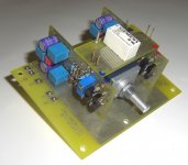

A fellow DIYer has put the JG Self linestage on a PCB so this is one more circuit i posted here that can now be build easily. Actually it is a modular system with a mother board, two line boards, the stereo-mono switch and the potmeter.
I like those 3D pcb's. Short connections, compact build. Nice!
jd