WuYit thank you so much.
When i was living in Macedonia i had a swedish friend. It seems that the most of swedish are nice 🙂
I hope you will be still here on this forum when ill build your project to tell you impressions.
Thanks
When i was living in Macedonia i had a swedish friend. It seems that the most of swedish are nice 🙂
I hope you will be still here on this forum when ill build your project to tell you impressions.
Thanks
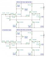
Considering the size of the bass-mid driver, the tweeter could be more suitable for reproducing those frequencies still with 12 dB roll-off. That´s what I think.
I mean, at least from what i have read, the cut-off frequency is also connected with distance between drivers, if that is time-space distinction then ok 🙂
WuYit....You amaze me with your utterly lack of any apparent knowledge of whats important in making loudspeakers sound right.....too complex... too much work.. and for what gain and for what purpose...money is fa better pent in making one great amplifer.. than making 3 poor ones... and keppeing things together as far as possible...
Even to get a sub woofer to time the music is virtually impossible...then making a complete active system is really asking for trouble...poorly spent money and time... all right maybe its very educational..but very musical I doubt it
Even to get a sub woofer to time the music is virtually impossible...then making a complete active system is really asking for trouble...poorly spent money and time... all right maybe its very educational..but very musical I doubt it
MiiB,
you haven´t excelled either so far. Please don´t miss the chance to reveal the secrets to driving loudspeakers properly.
you haven´t excelled either so far. Please don´t miss the chance to reveal the secrets to driving loudspeakers properly.
That´s true, and passive crossover indeed does not help improve the situation.Even to get a sub woofer to time the music is virtually impossible...
making perfect slopes in front of amplifiers...does not make drivers behave perfect...all must be tuned with the drive units aligned with the right time delay and physical distance.. then you can start working on the slopes and cross over points..... all must take place with the respect to the natural frequency response and dispersion of the drivers...and in all this you must understand the correlation to the human hearing and the fact that we are extremely sensitive to phase content maybe even more so than frequency content...so in crossover regions the drivers must not sum to perfect linearity..because then that area will stand out..
and and and....so so much more.....you dont car weather you cross at 80 or 140 hz....theres close to to an octave between the two.. one will carry the energy down the other will not, simply due the phase correlations between the drivers....
So when you lead others on.. at least be aware of what you do...
I have worked more than 20 years professionally with this...and my loudspeaker designs are recognized and respected throughout the world...
Member
Joined 2009
Paid Member
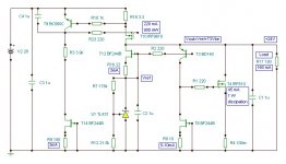
I don't really understand some of the posts about the power supply, I see some disagreements but not sure what the conclusion was. When I review the schematic I see a SE amp, the active device is loaded by a CCS and the speaker is in parallel with the active load - so the draw on the amp psu is a constant current and the filter caps are indeed outside of the audio path to first order. Isn't this a 'bog standard' configuration - what am I missing ?
... - so the draw on the amp psu is a constant current and the filter caps are indeed outside of the audio path to first order. Isn't this a 'bog standard' configuration - what am I missing ?
It is really not a standard case, since say 99% of schematics being in use do not posess this property.
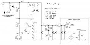
Here I post the "light" version of this follower. It does not need matching of transistors, mor reliable (less voltages, especially to the gate of VT1, and sounds in the few watts region even better than "senior" version. The only "contra", output power is smaller.
Attachments
Whats so so different is that the load is referenced to the regulated upper rail and not to GND...in that way the PSU caps i effectively taken out of the signal path..
glad that this is once again about the nice circuit...🙂
glad that this is once again about the nice circuit...🙂
WladimirK...
what is the upside of using the RF-device for the current source...?? and would there be any drawbacks by using a less costly mosfet in that position...??
what is the upside of using the RF-device for the current source...?? and would there be any drawbacks by using a less costly mosfet in that position...??
WladimirK...
what is the upside of using the RF-device for the current source...?? and would there be any drawbacks by using a less costly mosfet in that position...??
Could be you are right, and I would propose to try to substitute VT2 by 2SK1530.
But, I consider the VT2, VT3, VT4 section as a specific amplifier, and it must fit to VT1 properties. However, the difference could be negligible, I simply have not tested it.
Last edited:
MiiB,
the loudspeaker motor´s function is represented by the simple formula e = Blv, which defines a voltage source. For greatest linearity, any voltage source must approach the properties of an ideal voltage source and must be driven from a nearly ideal current source in direct and exclusive manner. Pertinence has been generally abandoned because of the need for practical convenience. Your company may have the opportunity to change the trend, but I haven´t seen any sign of it yet. It´s rather regrettable to talk about things of secondary importance, while neglecting the central point.
My speakers exhibit a gentle roll-off without the usual irregularities in that range, allowing very easy adaptation, I still preferred a higher ƒc point with a weak 6 dB slope. My experiences are not generally valid.
- Status
- Not open for further replies.
- Home
- Amplifiers
- Solid State
- Modified Follower-99 With HF Transistors