Gentlemen,
power supply rails serve as a (usually poor quality) AC ground. Taking a quick look at the Thevenin equivalent circuit can be helpful and hopefully would reduce the number of misconceptions.
You are making statements, for whome? Possibly, you would like to warn somebody, against what?
Why is the the rail a poor AC ground...since it also the reference for the active device.. it must be the best possible...
VladimirK
What do you think, what would be the limit of current and voltage for PF99 by Andrea Ciuffoli?
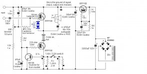
I would propose, for you specific heat sinks, to use a simple temperature probe, being an accessory of multimeter. Just press the sensor to metallic part of IRFP150 case and measure its temperature. Junction to case heat resistance of IRFP150 = 0,65 deg/W.
If you dissipates P = U x I watts on the device, and if you measure case temperature = T degrees in this specific situation, you can calculate the junction temperature Tj = T + 0,65*P.
You are allowed by the datasheet to increase P and correspondingly T until Tj remains less than 175 degrees. I would not advise to go higher than Tj=150 degrees.
I have noticed that in my DIY active crossover i have a holl of 12 dB in cut of frequency.
When im inverting the high-pass signal using softvare all is fine, the frequency responce is flat. I have a question, if I connect the tweeter oposite, could that solve the problem? Or i should search for some inverting circuit for high pass filter?
When im inverting the high-pass signal using softvare all is fine, the frequency responce is flat. I have a question, if I connect the tweeter oposite, could that solve the problem? Or i should search for some inverting circuit for high pass filter?
normally using 2.order LR slopes the summation is 180 degrees of...so the tweeter is mounted with opposite polarity...(midrange actually)
here's a link to a danish site with papers written by Steen Duelund...He's no longer with us but that doesn't make his thoughts less valid...much is to be gained loudspeaker understanding vise, if you digest thees two papers.
http://www.steenduelund.dk/?page=delefiltre&context=de2
here's a link to a danish site with papers written by Steen Duelund...He's no longer with us but that doesn't make his thoughts less valid...much is to be gained loudspeaker understanding vise, if you digest thees two papers.
http://www.steenduelund.dk/?page=delefiltre&context=de2
normally using 2.order LR slopes the summation is 180 degrees of...so the tweeter is mounted with opposite polarity...(midrange actually)
here's a link to a danish site with papers written by Steen Duelund...He's no longer with us but that doesn't make his thoughts less valid...much is to be gained loudspeaker understanding vise, if you digest thees two papers.
http://www.steenduelund.dk/?page=delefiltre&context=de2
I was trying severall times to open the link you've sent but without success unfortunately. Ill try to change the polarity of connection to tweeter and i expect to notice difference, in sence, i should hear more midrange frequencies..i think.
try this
http://tkhifi.homepage.dk/duelund-filter.pdf
Duelund Coherent Audio
sorry that you could not acces the theories behind the Synchrony filter...
http://tkhifi.homepage.dk/duelund-filter.pdf
Duelund Coherent Audio
sorry that you could not acces the theories behind the Synchrony filter...
And Vladimir....
Sorry for the noise in your thread....by no means meant intrusive....I do believe that theres something special here..a strong concept....though i still would like to make the speaker driven by alternating shunts...could be done very simple by a set of balancing input transformers..or by some of the nice preamplifier circuits made for F-4 and F-5..
While it might be seen as push-pull..it's not really..would rather look at at as inserting an active rail.. and thus loosing the need for output coupling caps.....rather different than splitting the signal and letting different devices handle the plus and minus side of the signal....
Thank You MiiB for the links, and You are right it is not a thread about crossovers. I apologize for the "noise" i made.
Member
Joined 2009
Paid Member
Whats so so different is that the load is referenced to the regulated upper rail and not to GND...in that way the PSU caps i effectively taken out of the signal path..
glad that this is once again about the nice circuit...🙂
OK, I understand. I have seen this topology more than once in the past so didn't consider it 'different' so didn't recognize what was generating the excitement.
The amp looks really good !
OK, I understand. I have seen this topology more than once in the past so didn't consider it 'different' so didn't recognize what was generating the excitement.
A concept we speak about here is well known, shunt-like approach. There is nothing conceptually new in audio for quite a long period, any "new" circuit can be decomposed into well known parts.
However, the shunt approach is almost unused, due to definite difficulties with its implementation. It is not convenient especially for mass production, class D is a way to future here.
For diyers and hobbists, the shunt-based schematics could be quite appealing, and I consider myself lucky since I have got sound that I listened only from the very top systems.
Did You ever had an ocassion to compare the sound of PF99 and Your design?
I can see that using fast devices like HF transistors with low input capacitance the responce should be faster. Can You send a meassuring results of square signal on 1KHz and 10KHz?
Did You ever had an ocassion to compare the sound of PF99 and Your design?
I can see that using fast devices like HF transistors with low input capacitance the responce should be faster. Can You send a meassuring results of square signal on 1KHz and 10KHz?
I did not test the original Andrea's schematics, there could be some difference. Important also is a choice of the output capacitors.
I observed square wave responce while selecting R1 and C2 values, using them limits the pass band (near 1 MHz) and makes flat the top of the square wave.
Of course, 1 and 10 kHz square waves are reproduced absolutely perfect (on my 50MHz scope I do not see any deflection from input signal after slight output signal level adjustment).
At 100kHz there is some deflection, the left top corner of the square wave becomes a bit rounded.
But, this is absolutely not decisive for final sound, much more specific properties are involved.
You have fast amp. I had an ocassion to measure Creek 4040 (i think it was that model) it was the only integrated amp with square responce like you described, simillar to yours. The sound of that amplifier was very close to sound of headphones, extremly clean.
MiiB,
Decoupling is isolation of amplifying stages in a common line. Separating the signal grounds (reducing the shared supply traces), gives minimum transmission of noise, interaction and interference.
Bypassing is reduction of high frequency current flow in a high impedance path.
Jean Hiraga used several hundred thousand uF of capacitance in his battery powered MC amp consuming about 10 mA of current. (In my view, he understood the essence of audio more than anyone else).
Mainly because of power supply insufficiencies. Power supply capacitors play a decisive role for the properties of signal ground and have a major impact on amplifier linearity.Why is the the rail a poor AC ground...since it also the reference for the active device.. it must be the best possible...
Decoupling is isolation of amplifying stages in a common line. Separating the signal grounds (reducing the shared supply traces), gives minimum transmission of noise, interaction and interference.
Bypassing is reduction of high frequency current flow in a high impedance path.
Jean Hiraga used several hundred thousand uF of capacitance in his battery powered MC amp consuming about 10 mA of current. (In my view, he understood the essence of audio more than anyone else).
Mainly because of power supply insufficiencies. Power supply capacitors play a decisive role for the properties of signal ground and have a major impact on amplifier linearity.
Decoupling is isolation of amplifying stages in a common line. Separating the signal grounds (reducing the shared supply traces), gives minimum transmission of noise, interaction and interference.
Bypassing is reduction of high frequency current flow in a high impedance path.
Jean Hiraga used several hundred thousand uF of capacitance in his battery powered MC amp consuming about 10 mA of current. (In my view, he understood the essence of audio more than anyone else).
Excuse me, but what you are saying here is not reality, concerning the signal ground (one is free to choose ground on plus or minus rail, there are detailed writings about this on tubecad, including explainations of this kind of follower), and references to Hiraga is not suitable as well. It is not difficult to speculate, but for solving the question it is better to assemble hardware.
Last edited:
- Status
- Not open for further replies.
- Home
- Amplifiers
- Solid State
- Modified Follower-99 With HF Transistors