WuYit
If you connect two drivers in series...and by adding a capacitor parallel over the low frequency driver and a coil over the tweeter you create frequency dependent shunts around the drive units...in the crossover region the two shunts have high impedance and the main current path is through the drive units that then share current...
rather different than normal filters where you treat each driver separately... simpler but at the same time much more complex as the driver parameters and play a much greater role...eg low resonance impedance peak in dome tweeters is an absolute no go....with the shunt type filters..
Vladimir,
have you built a high voltage shunt regulator?
In my preamp I used 100V 330mA "Zener substitute" on the basis of J200 transistor (plus few small bjt). The chain was as follows: 125V after diode bridge, 330 mA current source, "zener substitute" adjusted at 100V with two bjt, J200 for making zener substitute more powerful
MiiB,
I've been searching for meaning in this, can´t find any... What is a shunt type crossover in the first place?
I think he was talking about passive crossover saying shunt type of crossover, but if the shunt type of crossover is something different then typical passive crossover...i would like to know what's the difference.
I think he was talking about passive crossover saying shunt type of crossover, but if the shunt type of crossover is something different then typical passive crossover...i would like to know what's the difference.
I guess, for determining a difference, one should measure (or at least simulate) the frequency dependencies of impedance modulus and phase angle of the impedance vector. Big phase shifts, that are usual for serial high-order crossovers, cause difficulties for amplifier-speaker interaction.
Thanks MiiB, that´s a clear explanation, but there`s no theoretical reason why active crossover would give worse sound.
I tried active and passive crossover on same speakers, after few days listening to an active setup i noticed that something is missing, in mid-high region, i would explain it like a sound without life, clean but not interesting and i couldn't stand to listen to it more then 2-3 hours. Maybe an tube active crossover will be more pleasent to listen. For now i prefer (in my case) the passive speakers and SE amp. I think that IC's i was using are the reason for bad sound stage and lack of life in sound.
I know that in many articles and in theory active setup is described like better option. In my case it was not like that.
I know that in many articles and in theory active setup is described like better option. In my case it was not like that.
GoranB,
you could read this:
Series vs. Parallel Crossover Networks
Active crossover allows to drive loudspeakers appropriately.
Maybe it's time to revise your active crossover design.
you could read this:
Series vs. Parallel Crossover Networks
Active crossover allows to drive loudspeakers appropriately.
Maybe it's time to revise your active crossover design.
GoranB,
you could read this:
Series vs. Parallel Crossover Networks
Active crossover allows to drive loudspeakers appropriately.
Maybe it's time to revise your active crossover design.
Thanks for the link.
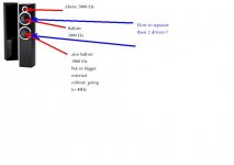
In my case its little difficult to build an active crossover because of dpeakers i have (cheap Wharfedale diamond 10.4 - 450 EUR) they are two and a half way speakers. the cut-off frequencies are 140Hz/3900Hz. The two mid bass drivers work together, one of them works down to 40Hz because of bigger cabinet (cabinets are internaly separated) for that driver is only a choke. The other part of cabinet consist mid-bass driver - choke in serie and capacitor in paralel, and tweeter C in series and L in paralel.
So, i build an act. crossover with cut-off frequency on 3900Hz/12dB. I didnt knew what to do with that bass going down to 40 HZ, so i connect it in parallel with mid-bass and i get 2-way speaker. The fact is i dont know the slope of original passive crossover in these speakers and sensitivity of each driver, so my act. crossover was far from perfect. For 2 mid bass drivers i used Marantz PM-44SE, and for tweeter PF99 and tube gain stage. I couldnt set the gains of these different topologies. Now you can realise how inperfect that project was.
I would appriciate any suggestion how to implement an active crossower for Wharfedale Diamond 10.4.
I have to say that using act. crossover bass was so clean and thight.
GoranB,
Your apprehension is justified. Discrete single-ended common drain stages is the way to go.I think that IC's i was using are the reason for bad sound stage and lack of life in sound.
GoranB,
couldn't you build a sub bass amp for the range up to say 80 Hz?
I can build, but explain what you had on mind?
Attachments
Just disconnect the lower drivers to use them bellow 80 Hz. I would build an ordinary constant voltage push-pull amp with bipolar output devices.
Just disconnect the lower drivers to use them bellow 80 Hz. I would build an ordinary constant voltage push-pull amp with bipolar output devices.
It would be easy to do, but cut-off between two bigger drivers is 140 Hz (Why eighty Hz?) and i dont know the slop (could be 6 db becouse is one choke only for the bass and midd bass according me have slop at 12 dB because of L and C filter) also what about sensitivities? How to set the gains for every amp? I dont have such a equipement to meassure the f. responce.
I was trying to find the sensitivities for drivers i have try hard but it seems too hard to find such a information.
You can eventually keep the 140 Hz high-pass filter or/and insert a series capacitor at the input of the amplifier. It´s not necessary to measure sensitivity, just make some adjustments afterwards. I would not go higher that 100 Hz anyway in order to achieve high resolution.
You can eventually keep the 140 Hz high-pass filter or/and insert a series capacitor at the input of the amplifier. It´s not necessary to measure sensitivity, just make some adjustments afterwards. I would not go higher that 100 Hz anyway in order to achieve high resolution.
You were right. Finally i understood how 2.5 way speakers work.
I have to use 6 mono-bloks and 3-way stereo active crossover.
For speakers i have it should be:
1. 0-140 Hz/6dB
2. 140-3900Hz/12dB
3. 3900-20000Hz/12dB
What you need is 80/100 Hz 18 dB active high-pass filter, 3900 Hz 12 dB active high-pass filter and 3900 Hz 12 dB active low-pass filter combined with 140 Hz 6 dB high-pass filter, right?
VladimirK,
What would happen if in the ZenV9 the grounds of the input and output were taken from the +B? Would it become a battery operation? Or, what does it take to make the ZenV9 battery operational?
GoranB,
You have certainly messed up with your crossover. Imo you'd better post in loudspeaker forum because you need to know a few things about the speaker stuff (Will need a dedicated thread to improve your speaker but it will worth it)
What you need is 80/100 Hz 18 dB active high-pass filter, 3900 Hz 12 dB active high-pass filter and 3900 Hz 12 dB active low-pass filter combined with 140 Hz 6 dB high-pass filter, right?
After some researching on net i realise that i need:
0-140 Hz / 6dB act. low pass filter
0-3900Hz / 12dB act low pass filter
and high pass act. filter above 3900Hz
- Status
- Not open for further replies.
- Home
- Amplifiers
- Solid State
- Modified Follower-99 With HF Transistors