The task of MFB is to ensure conformity of cone motion to signal input. That would apply correctly to sealed boxes and infinite baffling, correcting transient response, distortion, and resonances. But it wouldn't apply to a dipole sub for the system resonance (and related transient behaviour) which are main benefits of MFB.Found following amplifier on ebay that I want to try with my Dipole CFB/MFB subwoofers.
B.
...Just buy some Hypex gear, completely stable in a current setup.
That kind of talk about current drive seems odd to me. I say that because I understand (perhaps incorrectly) that the drive signal - whether current or good damping factor - to a highly inefficient device can't be much of a controller to the driver.
On the other hand, in so far as a "current drive amp" is really another way to design for "MFB by way of sensing the driver's back-EMF", it does make very good sense.
B.
The dipole speaker has a dipole correction of input signal of 6dB/oct before any corrections so that will work just fine. And the benefits of MFB in a Dipole speaker is just HUGE!!
Since the harmonics is also lifted above the fundamental signal.
Next benefit is that fact that dipole elements is moving closer to X-max and all drawbacks connected to big membrane movements.
So my idea is to combine the best subwoofer princip there is (i have used dipole subwoofer for more than 20 years by the way) with CFB and MFB and I look forward to the results. And i will for sure share my experience here with included measurements.

Time for an update.
I built 2 power amplifiers based on LM3886.
One ordinary with voltage feedback and one with current feedback using 0,3 ohms resistor to ground.
When i measure distortion from the same speaker element in same conditions but with different amplifier typologies there is a huge difference in distortion.
I did both acoustical measurements and fft of the signal over the speaker (shunt resistor 0,05 ohm).
Interesting!
Current drive reduces distortion in the loudspeaker!
3886 doesn´t give me enough voltage out so my plan is to use 2xTDA7293 (with +/- 50 Volt power supply), in parallell for each dipole woofer, making it 6xTDA7293 chip/channel. Those will be driven in current feedback mode obviusly, and later be fed by MFB corrected signal. Wish me good luck!
I can recommend you to listen to a chip amp with current feedback on a fullrange speaker! Magic!
Last edited:
Good stuff.
Any way to demonstrate how your drivers respond to pulses or tone bursts?
But I don't think there's any difference between what you are calling current feedback (across the .3-Ohm resistor) and motional feedback. But worth noting how simple it is to create current MFB with just a single resistor as compared to all the other methods.
Can you post your measurements please.
Also informative to see the output signal from the amp: with MFB, the signal to the speaker (normally clean as could be) but gets distorted as a mirror image to undistort the driver distortion (you can simply run the electric signal through REW just as you would a mic output).
Joe Rasmussen shows the basic schematic here:
Joe Rasmussen "Trans-Amp" - 40 Watt Transconductance "Current Amplifier"
The current feedback compensates for impedance variations due to temperature of the voice coil (dynamic distortion behaviour), you will gett eddy current in the pole piece that creates back EMK and other nasty distortion, the BL product changes with coil movement, specially in subwoofers at higher playback level. So current feedback is a good start, i´m waiting to finish the power stages when they arrive, in october/november.
Joe Rasmussen shows the basic schematic here:
Joe Rasmussen "Trans-Amp" - 40 Watt Transconductance "Current Amplifier"...
I see there is no voltage feedback, at least outside the amp (a little hard for me to feel that is OK in this application.). Which makes it, as you wanted, a current amp with a large output impedance.
But one very informative measurement is missing: the change in output impedance with the change in load. Is it negative?
BTW, when you say the BL product changes, that's the same as saying the driver is not quite linear. That's just the imperfection we get when we buy a driver. depending on quality True, that makes MFB just as imperfect as the motor but no worse at least for sine waves. Improved reaction to transients, suspension imperfections, and other bad motions with MFB is not dependent on the motor linearity in the same way.
Granted, all bets are off when the driver is pushed beyond its design.
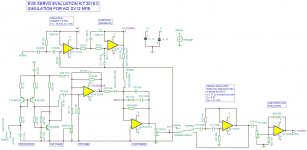
This post has been asleep for some time, but I have a question for Rscamp. In the very beginning of this thread you mention the optimization of R17 and C10, the loop shaping RC network of the EVE mixer circuit. I Have attempted to simulate that part of the EVE circuit in Vituixcad, but I seem to do something fundamentally wrong: the mixer shows a completely flat passband, and not the slight mountain/gain of post 20. Could you publish the circuit you used for that sim? Furthermore, although TINA looks nice, as Bolsert already pointed out, TINA does not display wrapped phase, making it visually somewhat more complicated for MFB loop sims.
Oops, I think I found my mistake: I did not properly connect the loop shaping network to earth. Prper connections require attention in Vcad. But I am still uncertain my sim is right, because gain vs phase looks too good to be true, so my question to Rscamp still stands..
Oops, I think I found my mistake: I did not properly connect the loop shaping network to earth. Prper connections require attention in Vcad. But I am still uncertain my sim is right, because gain vs phase looks too good to be true, so my question to Rscamp still stands..
Give me some time to look into this. I don't remember now what I did. 🙂
Take your time.....The TINA Sim in post 20 of this thread is what I referred to:
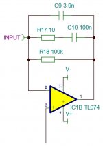
Loop Shaping Filter:
• Use 100n for C10
• Use 10 for R17
Loop Shaping Filter:
• Use 100n for C10
• Use 10 for R17
This post has been asleep for some time, but I have a question for Rscamp. In the very beginning of this thread you mention the optimization of R17 and C10, the loop shaping RC network of the EVE mixer circuit. I Have attempted to simulate that part of the EVE circuit in Vituixcad, but I seem to do something fundamentally wrong: the mixer shows a completely flat passband, and not the slight mountain/gain of post 20. Could you publish the circuit you used for that sim? Furthermore, although TINA looks nice, as Bolsert already pointed out, TINA does not display wrapped phase, making it visually somewhat more complicated for MFB loop sims.
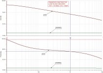
I think this circuit (or one very similar) was used for the simulation. I have also attached the analysis of just the Loop Filter portion of the circuit.
Does this help?
Attachments
Yes , I think so. If we load this circuit with your S&K closed box circuit, I assume we get the gently sloped "hill" of post 20. Will try this.
Would it be possible to display the transfer function of the circuit in 5dB /div?
Which circuit - Loop Filter or overall?
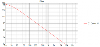
Loop filter transfer function and Bode plot: third (left to right) picture in post 212. Scale now seems to range from +120 dB to minus 10 dB.
It would be easier to view and interpret on 5 dB/div scale.
It would be easier to view and interpret on 5 dB/div scale.
Loop filter transfer function and Bode plot: third (left to right) picture in post 212. Scale now seems to range from +120 dB to minus 10 dB.
It would be easier to view and interpret on 5 dB/div scale.
Is this better?
Attachments
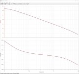
Yessss! This is what I need.
A question: @ 10 Hz the level is almost +95 dB. Is this an arbitrary level TINA default sets , or is it the result of some setting?
I have simmed the network in Vituixcad. Where I would assume the level @ 5 Hz to be around 0 dB, I get a level of + 116 dB @ 5 Hz.
I simply do not understand that high level, because the circuit -to my best of knowledge- does not amply, but functions as a low pass/leaky integrator.
This is more a question for the Vituixcad thread, I know, but was wondering whether you have an explanation for that level.In your sim is is also very high : 94.5 dB instead of 0 db.
For stability assessment sims, we need to analyze the phase margin unity gain/0 dB gain points. 80/90/100 dB levels do then not make much sense to me.
Eelco
Attachments
...A question: @ 10 Hz the level is almost +95 dB. Is this an arbitrary level TINA default sets , or is it the result of some setting?...
Eelco
Felco.
I set the input signal to an arbitrary value. The input signal definition from Tina is attached.
Attachments
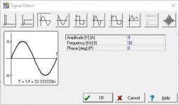
Maybe a silly question, but what does the transfer function then tell you if the level is arbitrary?
I am attempting to simulate the open loop gain of the MFB circuit in a step-by-step approach. So the first step is modelling of the sum section with its leaky integrator. The next step will be loading this section with the closed box S&K equivalent. But as long as I cannot drive the unity gain positions frequency-wise from that sim, phase assessment at unity gain is also impossible.
Do you have any suggestions?
- Home
- Loudspeakers
- Subwoofers
- MFB for ACI SV12 Drivers using Piratelogic Electronics