Try to battery feed your box and see if the ground loop disappear, i guess you can feed it with +/- 9 volt.
Could it be a ground loop between the power supply in that box and the source /amp through the rca grounds?
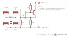
The StarBass V/2P as used by Rob follows this schematic:Do you know what the LF bandwidth limit is?
The Murata PKGS-00LDP1-R shocksensors typically have an capacitance of 0.7nF making a total of 1.5nF for the /2P variant Rob is using. R2 is set to 39M resulting in a lower pole of 2.72Hz. The FR on page 3 of the datasheet looks disturbing with output decreasing below 20hz already but doesn't seem to effect the usage of the sensor as accelerometer sofar.
Is the circuit similar to the one Phillips had used?
Almost with the addition of T1 to linearise the sensor output.
Correct, it is what Philips did with their original 532 design.If so, the -3dB down point might be the limiting factor. However, the EVE circuit can compensate for it using the shelving filter around IC1A. As an example, let’s say the -3dB down point of the accelerometer was 30Hz. The shelving filter can be used to compensate for this and provide flat response down to 3Hz...or whatever the user wants.
Don't think it's the recom as it looks like a hf switcher which typically hum around 20K 🙂 I would follow esl63's tip to do a battery powered test first. To rule out the hum is originating from the sensor you could try swap it for a 10K resistor connected directly to Eve.Or maybe this power supply is noisy? Or maybe I have done something dumb like installing the electrolytic filter caps backwards on the power rails? Or ???
btw, am following this thread closely but am kinda slow in responding due to being busy painting things😉
Attachments
Try to battery feed your box and see if the ground loop disappear, i guess you can feed it with +/- 9 volt.
Thanks, for the idea. I'll try this later today after getting a couple of 9V battery connectors.
And you do have the ac input next to the accelerometer wire so it may be bleed over also.
Thanks for the idea. One of the wires is fairly close to the accelerometer jacks so this might be an issue.
Don't think it's the recom as it looks like a hf switcher which typically hum around 20K 🙂 I would follow esl63's tip to do a battery powered test first. To rule out the hum is originating from the sensor you could try swap it for a 10K resistor connected directly to Eve.
Thanks, Chris. FYI. The hum is only an issue when I have the accelerometer feedback connected. So I don't know if terminating the accelerometer input with a resistor would show anything different.
I'll try the battery supply, but in the meantime I tried a couple of other things with some success.
First I disconnected the COM output of the power supply and COM inputs to the EVE boards from the chassis. (I had thought it would be good practise to use a star ground point for all these COM connections.) Then I electrically connected the MFB enclosure to the chassis of the power amplifier it is used with.
Each of the above steps reduced hum incrementally. With both steps, the hum is almost acceptable now but it would be nice to improve it a bit more.
I'm currently running a test with the Piratelogic 08S5-4 StarBass V equipped woofer and seem to bump into similar problems, approaching / touching this drivers aluminium cone also produces hum where earlier tests with a polypropylene cone equipped driver remained silent. Since most high-end low note drivers are equipped with a metallic cones this problem needs fixing. Since the StarBass itself already is fully shielded the primary suspect are the tinsel connection leads for which I'm looking for a shielded replacement. I'll let you know if I bump into something useful.Thanks, Chris. FYI. The hum is only an issue when I have the accelerometer feedback connected. So I don't know if terminating the accelerometer input with a resistor would show anything different.
I'm currently running a test with the Piratelogic 08S5-4 StarBass V equipped woofer and seem to bump into similar problems, approaching / touching this drivers aluminium cone also produces hum where earlier tests with a polypropylene cone equipped driver remained silent. Since most high-end low note drivers are equipped with a metallic cones this problem needs fixing. Since the StarBass itself already is fully shielded the primary suspect are the tinsel connection leads for which I'm looking for a shielded replacement. I'll let you know if I bump into something useful.
Ah. Good to know.
I tried powering the MFB electronics with +/- 9V batteries and the hum was just a little less but there wasn't a big difference. Unlike when using the recom power supply though connecting and disconnecting the common ground from the amplifier chassis to the MFB chassis made no difference.
I have a couple of observations with regard to the tinsel wires that I wanted to mention at some point.
1. In my case, because the speaker was large (12"), the tinsel wires supplied were just a bit short. I actually extended them with short runs of standard wire along the outside surface of the cone where it wouldn't require flexure.
2. The tinsel wires need only be very fine to carry the signal, but perhaps they shouldn't be so fine for larger drivers. The extreme flexibility of the fine tinsel wires works against you.
Instead of having a simple predictable flexure with excursions, at some frequencies I would be willing to bet the very fine wire starts to vibrate in more complex modes. I didn't use a strobotac to observe what is actually happening, but it seems highly likely the extreme flexibility over a longer run will result in more problems with the tinsel wires hitting the back of the cone and breaking at fixing points.
If the unsupported run for the accelerometer connection is similar to the run for the very heavy voice coil wires on a large drivers, I think this needs to be addressed by using tinsel wires for the accelerometer that are more similar in gauge to the voice coil wires.
Because I had the above concerns, I shortened the unsupported run by not penetrating the cone for the tinsel wires until nearly 3 inches radius from the centre on the ACI SV12 driver.
Attachments
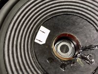
Here's how Rob@mfblabs is fixing his ultraflex mogami connection wires :Instead of having a simple predictable flexure with excursions, at some frequencies I would be willing to bet the very fine wire starts to vibrate in more complex modes. I didn't use a strobotac to observe what is actually happening, but it seems highly likely the extreme flexibility over a longer run will result in more problems with the tinsel wires hitting the back of the cone and breaking at fixing points.
Attachments
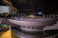
Interesting approach! However, I think with tinsel wires this complexity is unnecessary if the correct wire stiffness is selected for the unsupported span.
Next, let’s take a quick look at woofer response(phase in particular) and why it is problematic for wrapping a feedback loop around....
...Let me know if you have any questions so far.
I think the next step will be to pull in some real measured data and show trends of the OLTF and CLTF as the different EVE filters are adjusted.
Hi Bolserst. Thank you for educating us! My efforts over the last couple of weeks have not done the contributions you have made to this thread justice and for this I apologize. Rest assured that the knowledge you have passed on to us is being preserved for reference!
I am, however, pleased that this MFB experiment using Chris' tidy EVE boards has turned out as well as it has and I can use them in their current state of optimization. The EVE boards were designed for a certain generalized approach to optimization without detailed measurements and they seem to produce something that is going to work relatively easily. It is very cool to have another working MFB system! I want to move on and get the second stereo channel components modified, assembled, working, placed in the listening room to clean up the mess I have created and do some critical listening before the summer. 🙂
I am thinking of undertaking another MFB project that would utilize more of your expert advice later this year. For example, it may employ electronics (i.e. an amplifier) better suited to this application based on knowledge you have imparted on us. It might use an updated board from PirateLogic (if available) or the MFBLabs board or who knows, maybe even a fast DSP (nothing like getting way over my head!).
Bolserst, would Inuke 3000 work with Current feedback, and MFB?
Or do i have to mod input filter cap to extend the phase margin?
Planning to use 3*Dayton IB 15" elements (8ohm) in parallell = 2,7 Ohms and 0.1Ohm as current feedback measurement resistor, cabeling on top of that... 3 ohms in total.
Or should I put all 3 elements in series 24ohm..
48Volt swing would give 96W peak power over 24 ohm
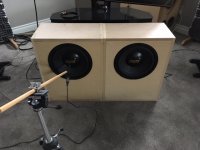
I put together the second subwoofer. Things went a lot quicker with the second one!
The first picture shows the two channels sitting on the floor. The measurement microphone can be seen positioned for near field measurement of the left channel.
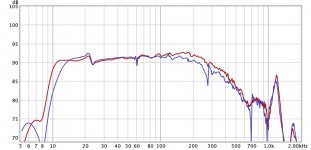
The high-pass (Rumble) filter was enabled on the EVE board to help address the resonant peak at 11 Hz. The table contained in piratelogic.eve.2018.0.manual.en.pdf has high pole frequencies starting at 21 Hz and a Q of 0.5. Instead of this, I used an online calculator and available components to produce an Fs of 16.8 Hz and Q of 0.65.
The second picture compares the left and right channel measurements with similar feedback settings. Red is right and blue is left. The right enclosure has ample damping material. The left enclosure has none. The room is known to have a first modal at around 22 Hz.
Note the relative absence of the 11 Hz resonant peak that appears in previous posts. This is interesting because it cannot be fully explained by the addition of the relatively gentle high-pass filter. Maybe this was largely due to the measurement setup previously used in the workshop?
The first picture shows the two channels sitting on the floor. The measurement microphone can be seen positioned for near field measurement of the left channel.
The high-pass (Rumble) filter was enabled on the EVE board to help address the resonant peak at 11 Hz. The table contained in piratelogic.eve.2018.0.manual.en.pdf has high pole frequencies starting at 21 Hz and a Q of 0.5. Instead of this, I used an online calculator and available components to produce an Fs of 16.8 Hz and Q of 0.65.
The second picture compares the left and right channel measurements with similar feedback settings. Red is right and blue is left. The right enclosure has ample damping material. The left enclosure has none. The room is known to have a first modal at around 22 Hz.
Note the relative absence of the 11 Hz resonant peak that appears in previous posts. This is interesting because it cannot be fully explained by the addition of the relatively gentle high-pass filter. Maybe this was largely due to the measurement setup previously used in the workshop?
Attachments
Can you show a FR for both without MFB ? I wouldn't be surprised to see the red one dramatically worsen - mfb has a tendency to eat away both driver as enclosure resonances - and to some extend even room modes.The second picture compares the left and right channel measurements with similar feedback settings. Red is right and blue is left. The right enclosure has ample damping material. The left enclosure has none.
Very nice results btw, pretty smooth @ 5dB steps !
... - and to some extent even room modes.
Very nice results btw, pretty smooth @ 5dB steps !
Yes, very impressive results and amazing matching too.
I've been wondering forever how MFB (which resembles active room acoustic control) interacts with room modes? The room modes must act on the cone like any other error. Anybody have a link?
B.
Last edited:
Good question, appears the peak wasn't caused by anything within the control loop then ... ?Note the relative absence of the 11 Hz resonant peak that appears in previous posts. This is interesting because it cannot be fully explained by the addition of the relatively gentle high-pass filter. Maybe this was largely due to the measurement setup previously used in the workshop?
Btw, there is some ultra flexible mogami shielded cable coming my way, I'll keep you updated on my hum findings 🙂
Can you show a FR for both without MFB ? I wouldn't be surprised to see the red one dramatically worsen - mfb has a tendency to eat away both driver as enclosure resonances - and to some extend even room modes.
Very nice results btw, pretty smooth @ 5dB steps !
It is working pretty well! I'll do another measurement when I get a chance. I'm pretty sure the resonance at about 280 Hz will be addressed by damping material. You can also see it in Post #67 where no damping material was used and it disappears in subsequent measurements after the damping material is added.
Good question, appears the peak wasn't caused by anything within the control loop then ... ?
That's the way it appears. Maybe 11 Hz input excited the natural frequency of the portable workbench the speaker was sitting on. Or something like that...
Btw, there is some ultra flexible mogami shielded cable coming my way, I'll keep you updated on my hum findings 🙂
Righto!
Last edited:
- Home
- Loudspeakers
- Subwoofers
- MFB for ACI SV12 Drivers using Piratelogic Electronics