Can you clarify what measured signals you are using, and what math you performed on them?
I am out and don't have access to respond to your post properly right now, but IIRC this was A/B where A was the response without feedback and B was the response with feedback.
Hopefully attached pic will clarify. To get the open-loop response that is needed to evaluate phase margins you need to measure the response around the whole signal path encompassed by mixer, filters, amp, woofer, accel, preamp-filters, and back to mixer. You can break the loop at any point to make this measurement.
Thanks for the clarification! I was a bit foggy on that.
I'm not aware of a way to import measurements into SPICE type circuit software, but it may be possible. What I do is measure from the power-amp input to the output of the accelerometer preamp. I import that into Excel where the closed loop response can be calculated for any combination of feedback filter, forward path filter, and gain. Once you figure out how to use Excel's intrinsic complex number capability, calculations like that are actually fairly simple.
Would this give me a start?
Just remembered that besides the HP filter at the input of the power amp, you may also want to increase the capacitor in the feedback path. According to this website: Master and the Clones | The Stereo Museum the schematic for your power amp should be very similar to the PALLADIUM LA-1200 taken from here UHER UMA 400 / Palladium LA 1200 reparieren, schaltplan, Hifi-Klassiker - HIFI-FORUM (Seite 2) If that schematic is correct, the input filter has turnover point of 0.7Hz and the feedback path has turnover point of 2.8Hz. You could measure response of amp to confirm. If you’re needing to improve LF phase margin, you might increase C404 to 47uF and C406 to 220uF.
Nice find! I didn't have as much luck finding any sort of schematic. I'll take a closer look at the board in the amp and see if anything looks familiar relative to this schematic.
You are amazing help on this topic! I think the image below accurately depicts our relative knowledge with you at the extreme right and me near the bottom of the trough.
Attachments

Ha, I was about to bring it up when I asked what amplfier your were using, bolserst is right, it's the reason there's an fully DC coupled UCD in the EVE manual wiring diagram and no output caps on the EVE board.Nice find! I didn't have as much luck finding any sort of schematic. I'll take a closer look at the board in the amp and see if anything looks familiar relative to this schematic.
Same here, glad you joined in bolserts, I understand the phase shift below Fbox but find the safe phase margin part difficult to convert to math. Hence the lack of description of it in the EVE manual.You are amazing help on this topic! I think the image below accurately depicts our relative knowledge with you at the extreme right and me near the bottom of the trough.
Last edited:
Ha, I was about to bring it up when I asked what amplfier your were using, bolserst is right, it's the reason there's an fully DC coupled UCD in the EVE manual wiring diagram and no output caps on the EVE board... glad you joined in bolserts...
Chris. I suggest a Vulcan mind meld to transfer knowledge from bolserts. 🙂
Chris. I suggest a Vulcan mind meld to transfer knowledge from bolserts. 🙂
A transfer from Bolserst would require a very big bandwidth channel.
Also, he's a really good person who helps us all so much.
B.
That would be a good startWould this give me a start?

Next would be to learn about all the available math functions that can operate with complex numbers. http://ecampus.matc.edu/lokkenr/pdfs/complex numbers.pdf
Also, here is an application note on using them to solve circuits Exact Circuit Analysis with Microsoft Excel - Application Note - Maxim
I’m not sure of your comfort level with Excel or electronics math. If needed, I could post an example spreadsheet that uses complex numbers to calculate frequency response for a few different types of filters. Just let me know.
I was finally able to get your TINA simulation to work on my laptop. Have been tied up with a few other priorities so have not had time to examine in detail. Should have time this weekend to play with it though. I will set up on example of the open loop response and how to evaluate LF and HF phase margin. Then trends can be seen as component values are adjusted.
Indeed, keeping things DC coupled as much as possible is the way to go for MFB. Every degree of phase margin at LF is precious if you want to maximize distortion reduction and keep the system stable.…it's the reason there's an fully DC coupled UCD in the EVE manual wiring diagram and no output caps on the EVE board.
Hopefully the examples and descriptions I will be posting using the SPICE model rscamp made of the EVE board will help clarify things. If the EVE becomes popular, we could also probably create an Excel spreadsheet where you can import measurements of the amplifier-woofer-accelerometer system and then simulate open and closed loop responses with the ability to change values of the difference filter elements and observe the effect on phase margins.…I understand the phase shift below Fbox but find the safe phase margin part difficult to convert to math. Hence the lack of description of it in the EVE manual.
That would be a good start
Next would be to learn about all the available math functions that can operate with complex numbers. http://ecampus.matc.edu/lokkenr/pdfs/complex numbers.pdf
Also, here is an application note on using them to solve circuits Exact Circuit Analysis with Microsoft Excel - Application Note - Maxim
I’m not sure of your comfort level with Excel or electronics math. If needed, I could post an example spreadsheet that uses complex numbers to calculate frequency response for a few different types of filters. Just let me know.
I was finally able to get your TINA simulation to work on my laptop. Have been tied up with a few other priorities so have not had time to examine in detail. Should have time this weekend to play with it though. I will set up on example of the open loop response and how to evaluate LF and HF phase margin. Then trends can be seen as component values are adjusted.
That's great! I think I left a component or two in the TINA model with multiple values for analysis (see asterisk *) so if you aren't immediately sure how to get rid of that let me know.
I'm comfortable with Excel to the extent that I use it frequently and have enabled the "Developer" tab for another purpose but electronics mathematics will definitely be new to me. I'm a mechanical engineer who can be dangerous on the electronics side and I'm not particularly strong on mathematics due to years of not using it. 🙂
...Hopefully the examples and descriptions I will be posting using the SPICE model rscamp made of the EVE board will help clarify things. If the EVE becomes popular, we could also probably create an Excel spreadsheet where you can import measurements of the amplifier-woofer-accelerometer system and then simulate open and closed loop responses with the ability to change values of the difference filter elements and observe the effect on phase margins.
Amazing! You are so helpful!
The simulation tool sounds like the ideal way to optimize the design. This tool is simply beyond me at the moment or for much longer than that - I'm not sure which. 🙂
I think we need a thread about an EVE-like board for the DIY crowd. I'm kind of stuck in building my own just now, so I'm in. And I'll take a shot at starting the thread.I hope there will be a current feedback option on the EVE board.
B.
where will that thread be? Subwoofer or analog line level?
I guess the best feedback would come from the latter.
I guess the best feedback would come from the latter.
I think we need a thread about an EVE-like board for the DIY crowd. I'm kind of stuck in building my own just now, so I'm in. And I'll take a shot at starting the thread.
B.
Sounds good. On a related note, I purchased a couple of the MFBLabs boards Chris mentioned in Post #102 to possibly try out at some point.
rschamp regarding your TINA simulation. Can you share the *.CIR file with me?
I want to do simulation as well with current feedback and dipole woofers.
Thanks 🙂
I want to do simulation as well with current feedback and dipole woofers.
Thanks 🙂
I was just reading Hans Klarskov article again (first time 1993 and then built ten subwoofers with his design) and since i did not at that time, had equipment measuring distortion, i found in his paper that Klarskov reduced distortion with only approx 50%.
From 5% down to 2,5%.
At the same time he extended the frequency range a lot of course.
I believe that we can do much better nowdays, 25 years later.
Better accelerometer, include current feedback, better calculation and simulation tools, and easy access to unlimited information sharing with wonderful people at DIY Audio!
Last edited:
Just a short status report:
Using TINA-TI for the first time turned out to be a bit confusing for me regarding phase which seemed to shift reference depending where in the circuit I was probing. I wasted more time that I should have searching for a wrapped phase option which would force the reference to 0deg. A post to the TINA-TI forum confirmed that this option was not available. [Resolved] TINA/Spice/TINA-TI: How to plot wrapped phase with TINA-TI? - Simulation, hardware & system design tools forum - Simulation, hardware & system design tools - TI E2E Community
Still working on a way around that, but for now I will export to Excel to perform the plotting.
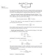
Attachment #1: Here is an summary and definitions of the terms used when discussing feedback control systems. The open-loop transfer function is what we need to measure to optimize phase margins. In amplifier design it is often called loop gain. What most people people call the open loop response (ie no feedback used) is usually called the feed-forward transfer function or simply the forward transfer function. Back in college days I used to use the acronyms OLTF, CLTF, and FFTF.
As mentioned in Post #120, the easiest way to measure the OLTF with the EVE setup is to input a signal to the power amplifier and measure the response coming out of terminal X1-5. Alternatively, if you measure the CLTF and FFTF as you did back in Post #92 you can calculate the OLTF.
OLTF = (FFTF-CLTF)/CLTF
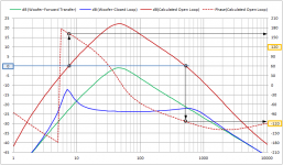
Attachment #2: Using your TINA-TI example, I exported the FFTF and CLTF responses to Excel and plotted them along with the calculated OLTF. Also shown is how to determine the phase margins be locating the point where the OLTF gain crosses 0dB and finding the phase at that point. Generally you would like to keep it within +/-120degrees or better to avoid response peaking and marginal stability. It is also desirable for the response slope to be first order(+/-6dB/oct) when it crosses 0dB to guarantee stability. In this case, you can see we have only about 20deg phase margin at LF (180deg - 160deg)
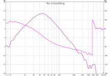
Attachment #3: I used REW to perform the same calculations with your data from Post #92.
I can provide some step-by-step screen shots of how to do this if needed...just let me know.
Tomorrow night I will post some trends on how the different filter components can be used to adjust(hopefully improve) the phase margins and increase the loop gain for increased distortion reduction.
Using TINA-TI for the first time turned out to be a bit confusing for me regarding phase which seemed to shift reference depending where in the circuit I was probing. I wasted more time that I should have searching for a wrapped phase option which would force the reference to 0deg. A post to the TINA-TI forum confirmed that this option was not available. [Resolved] TINA/Spice/TINA-TI: How to plot wrapped phase with TINA-TI? - Simulation, hardware & system design tools forum - Simulation, hardware & system design tools - TI E2E Community
Still working on a way around that, but for now I will export to Excel to perform the plotting.
Attachment #1: Here is an summary and definitions of the terms used when discussing feedback control systems. The open-loop transfer function is what we need to measure to optimize phase margins. In amplifier design it is often called loop gain. What most people people call the open loop response (ie no feedback used) is usually called the feed-forward transfer function or simply the forward transfer function. Back in college days I used to use the acronyms OLTF, CLTF, and FFTF.
As mentioned in Post #120, the easiest way to measure the OLTF with the EVE setup is to input a signal to the power amplifier and measure the response coming out of terminal X1-5. Alternatively, if you measure the CLTF and FFTF as you did back in Post #92 you can calculate the OLTF.
OLTF = (FFTF-CLTF)/CLTF
Attachment #2: Using your TINA-TI example, I exported the FFTF and CLTF responses to Excel and plotted them along with the calculated OLTF. Also shown is how to determine the phase margins be locating the point where the OLTF gain crosses 0dB and finding the phase at that point. Generally you would like to keep it within +/-120degrees or better to avoid response peaking and marginal stability. It is also desirable for the response slope to be first order(+/-6dB/oct) when it crosses 0dB to guarantee stability. In this case, you can see we have only about 20deg phase margin at LF (180deg - 160deg)
Attachment #3: I used REW to perform the same calculations with your data from Post #92.
I can provide some step-by-step screen shots of how to do this if needed...just let me know.
Tomorrow night I will post some trends on how the different filter components can be used to adjust(hopefully improve) the phase margins and increase the loop gain for increased distortion reduction.
Attachments
rschamp regarding your TINA simulation. Can you share the *.CIR file with me?
I want to do simulation as well with current feedback and dipole woofers.
Thanks 🙂
Sorry esl 63! I have been so busy with other things I haven't looked at this thread in a few days. There are two options for exporting the Netlist - one for Tina and one for PSpice. Which would you like?
Just a short status report:
Using TINA-TI for the first time turned out to be a bit confusing for me regarding phase which seemed to shift reference depending where in the circuit I was probing. I wasted more time that I should have searching for a wrapped phase option which would force the reference to 0deg. A post to the TINA-TI forum confirmed that this option was not available. [Resolved] TINA/Spice/TINA-TI: How to plot wrapped phase with TINA-TI? - Simulation, hardware & system design tools forum - Simulation, hardware & system design tools - TI E2E Community
Still working on a way around that, but for now I will export to Excel to perform the plotting.
Attachment #1: Here is an summary and definitions of the terms used when discussing feedback control systems. The open-loop transfer function is what we need to measure to optimize phase margins. In amplifier design it is often called loop gain. What most people people call the open loop response (ie no feedback used) is usually called the feed-forward transfer function or simply the forward transfer function. Back in college days I used to use the acronyms OLTF, CLTF, and FFTF.
As mentioned in Post #120, the easiest way to measure the OLTF with the EVE setup is to input a signal to the power amplifier and measure the response coming out of terminal X1-5. Alternatively, if you measure the CLTF and FFTF as you did back in Post #92 you can calculate the OLTF.
OLTF = (FFTF-CLTF)/CLTF
Attachment #2: Using your TINA-TI example, I exported the FFTF and CLTF responses to Excel and plotted them along with the calculated OLTF. Also shown is how to determine the phase margins be locating the point where the OLTF gain crosses 0dB and finding the phase at that point. Generally you would like to keep it within +/-120degrees or better to avoid response peaking and marginal stability. It is also desirable for the response slope to be first order(+/-6dB/oct) when it crosses 0dB to guarantee stability. In this case, you can see we have only about 20deg phase margin at LF (180deg - 160deg)
Attachment #3: I used REW to perform the same calculations with your data from Post #92.
I can provide some step-by-step screen shots of how to do this if needed...just let me know.
Tomorrow night I will post some trends on how the different filter components can be used to adjust(hopefully improve) the phase margins and increase the loop gain for increased distortion reduction.
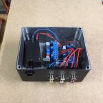
Awesome! I'll be getting back on this project in the next few days. I may take you up on your offer to provide instructions and I certainly look forward to any component optimizations for increased feedback gain, but first I'm going to better package what I have and clean up the mess on my bench. 🙂

- Home
- Loudspeakers
- Subwoofers
- MFB for ACI SV12 Drivers using Piratelogic Electronics