I must have missed something but why are you trying to go lower than 20 cycles?
If output below 20 Hz is required why not multiple larger diameter subs integrated in the floor or ceiling?
I have no use for infrasonic capability in this setup. Basically, we are just talking about an infrasonic filter in the circuit that ensures AC coupling and it's role in an infrasonic resonance that reduces how much feedback we can apply.
To me accelerometer based servo systems are the last frontier in our loudspeaker distortion reduction quest and will allow us to boldly hear what no one has heard before. Being part of this enterprise and being able to help you evangelize this tech fills me with pride.Yes, I'm both a pirate and a trekkieChris. Seriously, thank-you for making such products available.

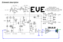
I'm just way to busy with my Little/One which just received a rave review from one of the premier dutch hifi sites, it's a Dutch article so google translate is your friend. Because of this I'm having a hard time finding the extra cycles to do an updated EVE anytime soon and have looked & found a solution for you, check attached images. The module displayed is fully through hole, has all the measurement points you can dream of and is a brainchild of Hans Mons who was the dev lead for the original Philips enclosures back in 1973. For more info please visit his mfblabs forum, again google translate is your friend.But, if you can squeeze it in, I would suggest just the addition of a header that can be used for dual duty - 1. to easily disconnect the accelerometer to run open loop and 2. to allow a connection point for monitoring of the acceleration signal so that the actual transfer function can be used to check the gain/phase margins.
Yes, 680n & 120K make 2 and not 20hz, the reasoning behind this 1:10 rule of thumb is that in order to minimize phase shift one should dimension a filter for 1/10 of the desired Fc. It's a well known trick used all over the place, for example see section 7.3.2 Input Impedance on page #14 of this document for more infoThe documentation indicates the pole for the existing values of 680n and 120k is 2 Hz rather than 20 Hz. But modelling in TINA does suggest a larger value of C4 could reduce the amplitude at resonance a little. You supplied 1 uF caps but I purchased 680n and used those. I just put in a 1 uF and it did reduce the amplitude at resonance slightly. I'll try an even larger value.
Attachments
![_DSC2281[1].jpg](/community/data/attachments/682/682300-185d10e974641ca3307631a17b17dff0.jpg?hash=GF0Q6XRkHK)
To me accelerometer based servo systems are the last frontier in our loudspeaker distortion reduction quest and will allow us to boldly hear what no one has heard before. Being part of this enterprise and being able to help you evangelize this tech fills me with pride.Yes, I'm both a pirate and a trekkie
What does being a pirate mean in the Netherlands? In Canada, piracy is an act of robbery. 🙂. On the other hand, being a trekkie has been, and always will be, held in great reverence. LOL
...I'm having a hard time finding the extra cycles to do an updated EVE anytime soon and have looked & found a solution for you, check attached images. The module displayed is fully through hole, has all the measurement points you can dream of and is a brainchild of Hans Mons who was the dev lead for the original Philips enclosures back in 1973. For more info please visit his mfblabs forum, again google translate is your friend.
Your attention please. Your attention please. Mr. bentoronto. Please report to mfblabs. Your thru hole solution is there waiting for you. 🙂
Thanks. But i am being lazy because the whole circuit isn't more complicated than a typical e-crossover. Piece of cake, if you also have a DSP for inevitable final in-situ EQ (attention rscamp)....Mr. bentoronto. Please report to mfblabs...
I got stuck last year trying to wire-up an R&D circuit that permitted going from an accelerometer input to a bridge velocity input with a single DPDT switch. It can be done.
B.
Good question which I'm getting more often these days, to answer it I'm preparing some extra about content, stay tuned.What does being a pirate mean in the Netherlands? In Canada, piracy is an act of robbery. 🙂.
Good question which I'm getting more often these days, to answer it I'm preparing some extra about content, stay tuned.
We'll keep our eye on you. 😉
I switched over to the 'real' power amplifier I was going to use with the MFB system. To my surprise, it has less gain than the receiver I was using for test with its volume < 100%. So now there is insufficient adjustment to reach 15 dB of feedback. It looks like the easiest way to fix this is to reduce the value of R11 which is in series with the MFB gain adjustment pot. Simulation indicates halving the value of R11 from 1k to 500 Ohms provides about 5.5 dB of additional gain.
Chris - would you concur that this is the simplest/best work-around?
Attachments
Decreasing the poweramp gain will lower the output of the Starbass, pretty much like switching from 4 to 8 ohm drivers. So yes, to bring the balance at the junction between R16 and R15 back to the point it was before you would need to increase the pxe gain. The proof is in the eating 😛
Do keep an eye on the signal levels though - clipped loops sound awfull
What poweramp were you using again ?
Do keep an eye on the signal levels though - clipped loops sound awfull
What poweramp were you using again ?
Last edited:
Decreasing the poweramp gain will lower the output of the Starbass, pretty much like switching from 4 to 8 ohm drivers. So yes, to bring the balance at the junction between R16 and R15 back to the point it was before you would need to increase the pxe gain. The proof is in the eating 😛
Do keep an eye on the signal levels though - clipped loops sound awfull
What poweramp were you using again ?
Thanks. I think I'll adjust R14 and C6 to achieve the increase in gain for the feedback. This way, I don't think the MFB pot will get more sensitive to adjustment.
The amplifier is in this post.
@rscamp,
Congrats on getting your MFB woofer operational.
I share your view that a means for measuring open-loop response is needed to optimize the stability-vs-gain for maximum distortion reduction.
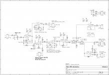
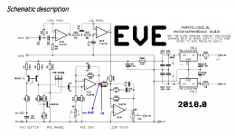
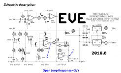
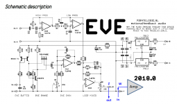
Attachment #1: Shows the ideal way to do this, breaking the loop at the red X. Input signal into R15 and measure the open-loop response at the output of opamp IC1A. With thru hole parts you would just lift one end of R15 to run the test. However, with surface mount parts this may be easier said than done.
Attachment #2: Since you are using REW, you can calculate the open-loop response based on two closed-loop measurements at points X and Y. Then use REW math functions to divide X by Y to get the open-loop response. If possible, use the second channel as a loop back timing reference to ensure the phase of the two signals share a common time reference. Commercial motional feedback woofer available sort of
Concerning the 13Hz Anomaly:
Pretty much all electret or condenser microphones contain a similar anomaly, but usually it is well below 10Hz. I believe it is related to the small air leak used for equalization of pressure inside the capsule with the changing ambient pressure and temperature. An open-loop response would confirm that it is not originating with the woofer or MFB electronics. Alternatively, you could measure another woofer in another box and see if the anomaly follows the microphone not the woofer.
Concerning LF stability:
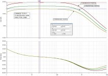
Anything you can do to avoid phase advance at low frequencies will improve phase margin and stability. Not having an open-loop measurement yet, you don’t know what your phase margin is, but I would guess it to be < 30deg based on the amount of peaking in the response. Lowering your sensor HP filter will help(0.1Hz would be good). Check what the HP filter is in the input of your amplifier, you may be able to gain some phase margin by increasing the size of the input coupling capacitor. Also, as you mentioned in post#90, increasing the value of C10 will retard the phase and improve LF phase margin. With C10 = 100nF the integration turn over frequency is about 16Hz. You might consider lowering it to 7Hz by increasing to C10 220nF. This will provide incremental improvement in LF phase margin. All these sources of phase advance stack up so it is worthwhile to hit them all if you can. I posted a set of measured open and closed loop trends for a matrix of loop gain and integration turn-over frequency. It may help understand the interplay between the two. Commercial motional feedback woofer available sort of
Not included in the trends is the effect of R17 which can help keep loop gain from falling too much at higher frequencies when you increase C10.
Similarly, pushing the turn over point of any LP filters in the loop as high as possible will avoid unnecessary phase lag and improve HF phase margins…which you have already taken advantage of by changing C6. Once you get an open-loop measurement, you will be able to see for sure how high you can push it while still avoiding intrusion from cone break-up modes.
Congrats on getting your MFB woofer operational.
I share your view that a means for measuring open-loop response is needed to optimize the stability-vs-gain for maximum distortion reduction.
Attachment #1: Shows the ideal way to do this, breaking the loop at the red X. Input signal into R15 and measure the open-loop response at the output of opamp IC1A. With thru hole parts you would just lift one end of R15 to run the test. However, with surface mount parts this may be easier said than done.
Attachment #2: Since you are using REW, you can calculate the open-loop response based on two closed-loop measurements at points X and Y. Then use REW math functions to divide X by Y to get the open-loop response. If possible, use the second channel as a loop back timing reference to ensure the phase of the two signals share a common time reference. Commercial motional feedback woofer available sort of
Concerning the 13Hz Anomaly:
Pretty much all electret or condenser microphones contain a similar anomaly, but usually it is well below 10Hz. I believe it is related to the small air leak used for equalization of pressure inside the capsule with the changing ambient pressure and temperature. An open-loop response would confirm that it is not originating with the woofer or MFB electronics. Alternatively, you could measure another woofer in another box and see if the anomaly follows the microphone not the woofer.
Concerning LF stability:
Anything you can do to avoid phase advance at low frequencies will improve phase margin and stability. Not having an open-loop measurement yet, you don’t know what your phase margin is, but I would guess it to be < 30deg based on the amount of peaking in the response. Lowering your sensor HP filter will help(0.1Hz would be good). Check what the HP filter is in the input of your amplifier, you may be able to gain some phase margin by increasing the size of the input coupling capacitor. Also, as you mentioned in post#90, increasing the value of C10 will retard the phase and improve LF phase margin. With C10 = 100nF the integration turn over frequency is about 16Hz. You might consider lowering it to 7Hz by increasing to C10 220nF. This will provide incremental improvement in LF phase margin. All these sources of phase advance stack up so it is worthwhile to hit them all if you can. I posted a set of measured open and closed loop trends for a matrix of loop gain and integration turn-over frequency. It may help understand the interplay between the two. Commercial motional feedback woofer available sort of
Not included in the trends is the effect of R17 which can help keep loop gain from falling too much at higher frequencies when you increase C10.
Similarly, pushing the turn over point of any LP filters in the loop as high as possible will avoid unnecessary phase lag and improve HF phase margins…which you have already taken advantage of by changing C6. Once you get an open-loop measurement, you will be able to see for sure how high you can push it while still avoiding intrusion from cone break-up modes.
Attachments
Last edited:
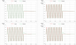
As we have discussed several times in the past, the way tone bursts look(and sound) has nothing to do with MFB taking a “firm hand” with the driver, although that is exactly the picture I had in my mind when I starting experimenting with it. Commercial motional feedback woofer available sort of…The MFB burst starts with a visibly (and probably audibly) bigger kick. That is what "fast bass" means…With MFB muscling the driver around, tone burst results can look very different according to the freq chosen.
When stable, a MFB woofer system is a minimum phase device. As such, it can be thought of as just a black box with an input and an output. Measure the impulse response, or frequency response, and you have determined how every other signal (tone burst etc) will look like when it is “processed” by the black box. However, it tells you nothing about what is in the black box. It could be a MFB system, or it might be just a DSP equalizing the response.
By way of example, I took the responses plotted in Post #92 and curved traced them. Then performed IFFT to get the impulse response. Finally, ran a 5 cycle 50Hz tone burst thru the impulse response by convolution and compared with the measured tone bursts plotted in Post #94 (see Attachments #1 & #2). Not a perfect match, but amazingly close considering the curve tracing and required LF extrapolation/interpolation of the response data. If rscamp had posted the impulse response file in *.wav format, it would have matched perfectly. In fact once you have the impulse response, you can calculate the burst response for any frequency much quicker and easier than measuring...well, if you have access to convolution software.
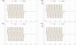
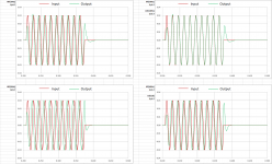
Indeed, the "super fast" beginning and end of a LF tone burst contains HF information. A spectrogram display(frequency content vs time) of a burst illustrates this nicely…I have one somewhere but can’t locate it at the moment. When a woofer includes a LP filter, you will see a rate limit to the slope of the burst onset dictated by the LP filter frequency. I managed to locate a set of trend plots I made some years ago showing 10 cycle 60 Hz burst for a range of LP and HP filter settings.Not exactly clear to me why a sub (or any driver) should play nice tone bursts. The burst starts with a super fast acceleration and ends with a super fast abrupt stop.
Attachment #3: LP(2Hz), LP(2Hz) + HP(120Hz), LP(10Hz), LP(10Hz) + HP(120Hz)
- notice how the slope of the burst onset is limited by the LP filter
Attachment #4: LP(30Hz), LP(30Hz) + HP(120Hz), LP(60Hz), LP(60Hz) + HP(120Hz)
- notice the LP filter advancing the phase, and the HP filter retarding the phase
Attachment #5: LP(60Hz, Q=1.4), LP(60Hz, Q=1.4) + HP(120Hz), LP(100Hz), LP(100Hz) + HP(120Hz)
- notice the underdamped LP 60Hz filter makes the burst amplitude take longer to build and die away
As suggested in the link above I still highly recommend:
“If you have access to a mini-DSP, DCX2496, or similar it might be educational for you to observe some tone bursts passed thru them. Then experiment with different HF and LF roll-off filters to emulate the response of typical sealed or ported box alignments. The effect on the start and stop of tone bursts even for frequencies in the middle of the subwoofer passband might surprise you. If at some later date you see similar time history traces from a woofer measurement, you might consider that it is not necessarily a woofer in need of a firm hand causing the tone burst to look that way but rather a simple consequence of the overall response(magnitude and phase).
Sooo…why use MFB if similar results can be had with equalization?
- Distortion reduction as excursion increases at lower frequencies, shown nicely in Post #93.
- Maximizes LF SPL for a given woofer/enclosure size and desired distortion threshold.
- Immunity from variation in woofer parameters (not important for DIY)
- It’s fun and intellectually satisfying! (not important for OEM)
Attachments

Last edited:
Thank you so much for taking the time to provide this helpful input bolserst. Much appreciated!
Thanks! This has been a learning experience for sure. I have a fairly good handle on the physics but there were a lot of firsts in this for me and it took many hours to work through them - dissecting a driver to install an accelerometer, using REW for testing, using a circuit analysis tool (TINA) including making a circuit model for a closed box speaker and applying feedback. This last thing was the biggest stretch for me because I'm not an electronics guy.
I read several control theory articles on determining phase and gain margins and was anticipating doing this analysis as part of this project. Due to inexperience it wasn't until later that I realized it would be tricky to get the access to do this with the EVE board. I thought of soldering some 30 AWG wire to a flying 2-pos header to get access at the output of IC1A as you suggest. But I kinda petered out on this when I started to have some success.
Hold the phone. You can do math within REW? Where is this capability? A couple of days ago I thought it would be cool to derive a plot of the feedback factor vs frequency but didn't see anything in the Help on this. I could see maybe exporting the data and using Excel but I haven't looked into this yet.
I have been observing the anomaly under all conditions - different amplifier, different measuring distance, open loop, closed loop, etc. I too thought the microphone was the culprit but didn't know why. The UMIK-1 specs only claim performance down to 20 Hz so a few days ago I searched for information on using this microphone below 20 Hz. I didn't find anything very useful so I did a very simple experiment. Without feedback below Fs, the amplitude of the driver motion should become a constant (compliance-dependent region). I closely observed the speaker amplitude as I manually swept the frequency downward and I saw this constant amplitude with no anomaly in motion around 13 Hz. So by this observation I ruled out a problem with the speaker in my own mind. Now your information fills in the gap. Thanks!
There is a lot to think about in your comments about LF stability so I'll digest that some more and then comment in another post.
@rscamp,
Congrats on getting your MFB woofer operational.
Thanks! This has been a learning experience for sure. I have a fairly good handle on the physics but there were a lot of firsts in this for me and it took many hours to work through them - dissecting a driver to install an accelerometer, using REW for testing, using a circuit analysis tool (TINA) including making a circuit model for a closed box speaker and applying feedback. This last thing was the biggest stretch for me because I'm not an electronics guy.
I share your view that a means for measuring open-loop response is needed to optimize the stability-vs-gain for maximum distortion reduction.
Attachment #1: Shows the ideal way to do this, breaking the loop at the red X. Input signal into R15 and measure the open-loop response at the output of opamp IC1A. With thru hole parts you would just lift one end of R15 to run the test. However, with surface mount parts this may be easier said than done.
I read several control theory articles on determining phase and gain margins and was anticipating doing this analysis as part of this project. Due to inexperience it wasn't until later that I realized it would be tricky to get the access to do this with the EVE board. I thought of soldering some 30 AWG wire to a flying 2-pos header to get access at the output of IC1A as you suggest. But I kinda petered out on this when I started to have some success.
Attachment #2: Since you are using REW, you can calculate the open-loop response based on two closed-loop measurements at points X and Y. Then use REW math functions to divide X by Y to get the open-loop response. If possible, use the second channel as a loop back timing reference to ensure the phase of the two signals share a common time reference. Commercial motional feedback woofer available sort of
Hold the phone. You can do math within REW? Where is this capability? A couple of days ago I thought it would be cool to derive a plot of the feedback factor vs frequency but didn't see anything in the Help on this. I could see maybe exporting the data and using Excel but I haven't looked into this yet.
Concerning the 13Hz Anomaly:
Pretty much all electret or condenser microphones contain a similar anomaly, but usually it is well below 10Hz. I believe it is related to the small air leak used for equalization of pressure inside the capsule with the changing ambient pressure and temperature. An open-loop response would confirm that it is not originating with the woofer or MFB electronics. Alternatively, you could measure another woofer in another box and see if the anomaly follows the microphone not the woofer.
I have been observing the anomaly under all conditions - different amplifier, different measuring distance, open loop, closed loop, etc. I too thought the microphone was the culprit but didn't know why. The UMIK-1 specs only claim performance down to 20 Hz so a few days ago I searched for information on using this microphone below 20 Hz. I didn't find anything very useful so I did a very simple experiment. Without feedback below Fs, the amplitude of the driver motion should become a constant (compliance-dependent region). I closely observed the speaker amplitude as I manually swept the frequency downward and I saw this constant amplitude with no anomaly in motion around 13 Hz. So by this observation I ruled out a problem with the speaker in my own mind. Now your information fills in the gap. Thanks!
There is a lot to think about in your comments about LF stability so I'll digest that some more and then comment in another post.
Concerning LF stability:
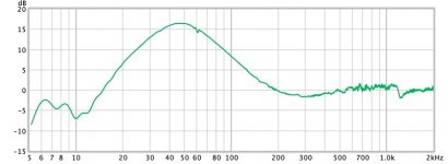
Anything you can do to avoid phase advance at low frequencies will improve phase margin and stability. Not having an open-loop measurement yet, you don’t know what your phase margin is, but I would guess it to be < 30deg based on the amount of peaking in the response.
Being a closed box system, the speaker has 180 deg. phase advance as it passes down through Fs. Is it not desirable for the loop filter to mimic this to keep these from getting too far out of phase? The EVE circuitry certainly has this characteristic. When "optimizing" the loop filter in TINA, I looked for a similar phase advance for the loop filter relative to the speaker in combination with good attenuation at higher frequencies to avoid oscillation at higher frequencies due to a resonant condition in the accelerometer mount or whatever ugliness might be up there.
Lowering your sensor HP filter will help(0.1Hz would be good).
Yes. Modelling with TINA and quickly trying a slightly larger value for C4 seems to confirm this. I ordered a much larger cap to try out. I'm guessing from what I have seen so far it might be worth another couple of dB of feedback gain.
Check what the HP filter is in the input of your amplifier, you may be able to gain some phase margin by increasing the size of the input coupling capacitor.
It would have taken me a very long time to even think of this! 🙂
Also, as you mentioned in post#90, increasing the value of C10 will retard the phase and improve LF phase margin. With C10 = 100nF the integration turn over frequency is about 16Hz. You might consider lowering it to 7Hz by increasing to C10 220nF. This will provide incremental improvement in LF phase margin.
I did try a larger value of C10 (150 nF) and didn't see any improvement in the LF resonance. Modelling in TINA also shows only a very slight difference in LF phase response by going to 220n. Am I missing something?
Thanks. I think I'll adjust R14 and C6 to achieve the increase in gain for the feedback. This way, I don't think the MFB pot will get more sensitive to adjustment.
The amplifier is in this post.
Update:
C6 and R14 interact so for a near identical transfer function with more gain through "PXE GAIN" I increased R14 from 10k to 22k and reduced C6 from 22n to 10n. Feedback gain increased enough to provide sufficient adjustment with the MFB pot with no observed detrimental effects.
As we have discussed several times in the past, the way tone bursts look(and sound) has nothing to do with MFB taking a “firm hand” with the driver, although that is exactly the picture I had in my mind when I starting experimenting with it....
When stable, a MFB woofer system is a minimum phase device. As such, it can be thought of as just a black box with an input and an output. Measure the impulse response, or frequency response, and you have determined how every other signal (tone burst etc) will look like when it is “processed” by the black box. However, it tells you nothing about what is in the black box. It could be a MFB system, or it might be just a DSP equalizing the response....
Great to have input from Bolserst. As Alexander Pope said of Newton, 'Nature and Nature's laws lay hid in night:God said, Let Newton be! and all was light.'
Doggerel aside, let us say MFB can be considered "nothing but" a black box with a perfect speaker and band filtering. Aside from inconceivably sophisticated fixin', how else to make a perfect speaker?
Granted, one can conjure up tone bursts resembling the MFB which meet my tired-eye-ball standard using filters. But MFB seems the coherent way to do it and else besides.
rscamp: your attachment in post #114 seems to have a Mac-unfriendly TSC designation, after unzipping.
B.
Last edited:
rscamp: your attachment in post #114 seems to have a Mac-unfriendly TSC designation, after unzipping.
B.
TINA-TI is a Windows program. You can download it here.
I use Macs when I can and PCs when I must. 🙂
The math functions are limited to operations between two measurements....Hold the phone. You can do math within REW? Where is this capability? A couple of days ago I thought it would be cool to derive a plot of the feedback factor vs frequency but didn't see anything in the Help on this. I could see maybe exporting the data and using Excel but I haven't looked into this yet.
You can find them in the control panel of the “All SPL” plot. All SPL Graph
It just dawned on me that you don’t have to break the loop at the traditional feedback point to measure the open loop response. You can break the loop anywhere along the path and get the same results. In your case, you pretty much have one built in at the interface between the EVE board and your power amp. Be sure to calibrate your soundcard with loop back test so that a gain of 1x will show up as 0dB in the open-loop plot. Getting set up for measuring… I thought of soldering some 30 AWG wire to a flying 2-pos header to get access at the output of IC1A as you suggest. But I kinda petered out on this when I started to have some success.
Correct, for closed box system phase advances +180deg below resonance, and retards a maximum of -90deg at higher frequencies due to voice coil inductance. Ideally, you want the loop filter to move the +180deg phase at LF down toward +90deg without moving the -90deg phase at HF any further negative. With phase in the +90deg to -90deg range for gains > 1x you would have an extremely stable feedback design. In reality, you will usually wind up with something more like +120deg to -120deg…much lower phase margin than that and you will start to see significant peaking hinting at the approach of instability.Being a closed box system, the speaker has 180 deg. phase advance as it passes down through Fs. Is it not desirable for the loop filter to mimic this to keep these from getting too far out of phase?
I will get TINA loaded on my laptop tonight and check out the circuit you posted.I did try a larger value of C10 (150 nF) and didn't see any improvement in the LF resonance. Modelling in TINA also shows only a very slight difference in LF phase response by going to 220n. Am I missing something?
Attachments
No argument here. The purpose of my post was not to denigrate MFB, but to clarify what it is and isn’t doing. Any improvements in impulse response or tone burst tracing it provides is merely due to the frequency/phase response of the MFB system. In this regard, it isn’t doing anything that couldn’t be accomplished with an equalizer. But as you alluded to, MFB also brings with it distortion reduction.…MFB seems the coherent way to do it and else besides.
The math functions are limited to operations between two measurements.
You can find them in the control panel of the “All SPL” plot. All SPL Graph
Cheers!
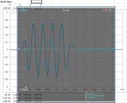
I guess I wasn't searching for the right terms in Help for REW. The plot I was thinking of doing is now done! See the image below. I like this because it shows feedback factor vs frequency. It could have a small absolute error because I matched levels for the two curves (with and without feedback) by eye.It just dawned on me that you don’t have to break the loop at the traditional feedback point to measure the open loop response. You can break the loop anywhere along the path and get the same results. In your case, you pretty much have one built in at the interface between the EVE board and your power amp. Be sure to calibrate your soundcard with loop back test so that a gain of 1x will show up as 0dB in the open-loop plot. Getting set up for measuring
When observing the accelerometer response, wouldn't the result at X1-5 be coloured by the Loop Mixer response? And if the feedback loop is broken, no acceleration signal will be seen at X1-5 at all. But again, maybe I'm missing something...
Correct, for closed box system phase advances +180deg below resonance, and retards a maximum of -90deg at higher frequencies due to voice coil inductance. Ideally, you want the loop filter to move the +180deg phase at LF down toward +90deg without moving the -90deg phase at HF any further negative. With phase in the +90deg to -90deg range for gains > 1x you would have an extremely stable feedback design. In reality, you will usually wind up with something more like +120deg to -120deg…much lower phase margin than that and you will start to see significant peaking hinting at the approach of instability.
This makes me think that the next logical step is to somehow take a representation of the actual transfer function of the feedback and put that into the circuit analysis software to find the actual gain and phase margins. Is that possible?
I will get TINA loaded on my laptop tonight and check out the circuit you posted.
Cheers! When you see something you don't like, just remind yourself the schematic was entered by a mechanical guy. 🙂
Attachments
Can you clarify what measured signals you are using, and what math you performed on them?…The plot I was thinking of doing is now done! See the image below. I like this because it shows feedback factor vs frequency.
Hopefully attached pic will clarify. To get the open-loop response that is needed to evaluate phase margins you need to measure the response around the whole signal path encompassed by mixer, filters, amp, woofer, accel, preamp-filters, and back to mixer. You can break the loop at any point to make this measurement.When observing the accelerometer response, wouldn't the result at X1-5 be coloured by the Loop Mixer response? And if the feedback loop is broken, no acceleration signal will be seen at X1-5 at all. But again, maybe I'm missing something...
I'm not aware of a way to import measurements into SPICE type circuit software, but it may be possible. What I do is measure from the power-amp input to the output of the accelerometer preamp. I import that into Excel where the closed loop response can be calculated for any combination of feedback filter, forward path filter, and gain. Once you figure out how to use Excel's intrinsic complex number capability, calculations like that are actually fairly simple.This makes me think that the next logical step is to somehow take a representation of the actual transfer function of the feedback and put that into the circuit analysis software to find the actual gain and phase margins. Is that possible?
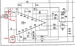
Just remembered that besides the HP filter at the input of the power amp, you may also want to increase the capacitor in the feedback path. According to this website: Master and the Clones | The Stereo Museum the schematic for your power amp should be very similar to the PALLADIUM LA-1200 taken from here UHER UMA 400 / Palladium LA 1200 reparieren, schaltplan, Hifi-Klassiker - HIFI-FORUM (Seite 2) If that schematic is correct, the input filter has turnover point of 0.7Hz and the feedback path has turnover point of 2.8Hz. You could measure response of amp to confirm. If you’re needing to improve LF phase margin, you might increase C404 to 47uF and C406 to 220uF.
Attachments
- Home
- Loudspeakers
- Subwoofers
- MFB for ACI SV12 Drivers using Piratelogic Electronics