I think I discovered my mistake: I forgot to insert a resistor of apprx 9 kOhms between the signal generator and the min input of the opamp.
That brings down circuit gain to normal values.
That brings down circuit gain to normal values.
For dipole speaker with fs 20Hz and Qts 0,65
What is the ideal loop shape filter values of R17 and C10?
What is the ideal loop shape filter values of R17 and C10?

No, maybe 20dB, after Eq i have very good frequency response, i´m not using the CFB and MFB for frequency correction, only for distortion reduction.
If I understand you correctly, first of all you are planning to correct the woofers outside the MFB loop, and then apply MFB to the (mildly?) corrected system? I suppose you then keep the most distorted part of the woofers new passband outside the loop. I.m.o. that defies the purpose of MFB. Excursion is still excursion, whether one applies MFB or not.
Actually I have my doubts whether that is possible at all, but maybe that remark shows my lack of fundamental understanding control theory and stability issues...
Actually I have my doubts whether that is possible at all, but maybe that remark shows my lack of fundamental understanding control theory and stability issues...
Dipole woofers lack efficiency at low frequency. So it will have a roll off.
Musik from my source will then have frequency correction, so i implemented dipole correction for 20 years ago. And it works great! Giving 15dB more headroom for the Quads making them more dynamic. etc, etc,,
Dipole woofer in itself is superior to other low frequency generators since the interact with the room much better acoustically, and has so many advantages sound-vice so i will never go back to anything else.
However the high excursion at low frequency needed to play at decent volume gives distortion, playing at low volume they blend in well with (modified) QUAD ESL-63, but playing Infected Mushrooms at 100dB the coloration becomes apparent from the subs. Current feedback reduces distortion, and in combination with Piratelogic MFB I expect to reach 20-25dB less distortion in total. I have seen other people reaching this.
It is very tempting to start a discussion about monopoles vs dipoles in the 20-80 Hz range, but I will resist that... Correcting dipole roll off outside the MFB loop will not give you the 20-25 dB distortion reduction you aim for. Furthermore, a 20-25 dB distortion reduction will require a somewhat more sophisticated loop circuitry than the basic R17/C10 integrator in your specific case, with the -uncorrected- relatively high dipole roll off @100Hz. You simply need more local loopgain than the basic integrator circuit can realize without running into insufficient phase margin@unity gain problems.
Have a look at the att.s 137 and 147 of this thread, posted by our unsurpassable Bolserst.
Have a look at the att.s 137 and 147 of this thread, posted by our unsurpassable Bolserst.
Attachments
Actually between 12Hz and 27 Hz i use my garage 100 thousand liters (25 thousand Gallon), as an Infra sound sub, using 4*15" woofers in the wall between garage and listening room.
At those frequencies you have no standing waves, you just pressurize the room.
Lets focus on R10 and C17
At those frequencies you have no standing waves, you just pressurize the room.
Lets focus on R10 and C17
Working on getting you the all new and improved EVE 2020.


- Adjustable accelerometer bias voltage
- Input buffer
- Low noise pxe buffer
- Pxe phase switch
- Through-hole loop shaping parts & rails bleeders
- Max rails +/- 60V
- Open/closed loop mode switch
- led loop limiter
- Symmetric line out
- ne5532 opamps
- 50x50 mm
- JST headers
Last edited:

Just ordered these, ETA week 25Working on getting you the all new and improved EVE 2020.
- Adjustable accelerometer bias voltage
- Input buffer
- Low noise pxe buffer
- Pxe phase switch
- Through-hole loop shaping parts & rails bleeders
- Max rails +/- 60V
- Open/closed loop mode switch
- led loop limiter
- Symmetric line out
- ne5532 opamps
- 50x50 mm
- JST headers


Footnote about OB subs and MFB. I had a 15-inch woofer on a large panel with an irregular perimeter for a few years. While I like the OB sound for mains a lot, not sure I found anything special about sub's sound quality or performance in a room otherwise. (Much easier to change boxes around to good locations than large Ops.)
1. The output from an OB sub includes a substantial "free" boost at the natural free-air resonance of the driver. Sure can change the non-EQ FR plots. This is not discussed in fevered discussions of Linkwitz Transform but it ought to change the LT, at least in modelling. (I'd like to hear where this shows up in esl63's fabulous system?)
2. The real obstacle is that you need immense cone motion with an OB sub if it is to go low freq. With MFB, you can get error correction, of course. But if the cone starts going seriously out of its operating range, hopeless for MFB to be anything but a disaster.
B.
1.
Last edited:
Well, Ben,
The plots of ESL 63 do not show the boost you are referring to. Modern low Qts drivers will have a very controlled roll off. Exactly where there are large excursions, MFB will immensely improve the system if substantial feedback is applied at least.
Please correct me if I am wrong, but I still assume one would need over 30 dB loopgain to have any useful correction of the OB woofers. Maybe one of the experts ( Bolserst?) could chime in here: I am still at the beginning of my MFB learning curve and looking at a steep hill...
...The plots of ESL 63 do not show the boost you are referring to. Modern low Qts drivers will have a very controlled roll off. ...
Maybe one of the experts ( Bolserst?) could chime in here: I am still at the beginning of my MFB learning curve and looking at a steep hill...
Puzzling there is no boost at resonance. Maybe gets lost in the room eigentones and LT boost. The free-air cone motion peak is not gradual when I measure a sub in free-air.
MFB for OB if you are aiming for real low freq might be tricky. It can be done, I suppose, but a stretch unless you have enough cone surface to avoid big cone motions.
B.
Thats why i have the "Infra sub" below 27Hz, so i decouple the dipoles and pressurize the room at frequencies where I got no resonances du to the long wavelengths.MFB for OB if you are aiming for real low freq might be tricky. It can be done, I suppose, but a stretch unless you have enough cone surface to avoid big cone motions.
B.
Am working to include comments, tips & tricks from this thread - thank you all! - into the updated EVE2020 manual, while reading I bumped into bolserst post #148 which says:
With regards to C1 and R2, these are for keeping rf artefacts from entering the servo loop which could proof troublesome especially when long leads are used between EVE and the Starbass.
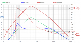
The non inverting setup around IC1a was chosen to allow for a more flexible change of pxe.gain, using an inverting setup would require adjustment of C6 each time R14 is changed. Initially I had IC1a gain fixed and pxe level set by means of a potmeter at the output of IC1a but found the current solution less noisy and easier to work with.Next, let’s take a quick look at woofer response(phase in particular) and why it is problematic for wrapping a feedback loop around. Then, describe some of the tools(ie filters) available to deal with the phase problems. Finally describe what the difference is between putting filters in the feed-forward path(between mixer and woofer) or in the feed-back path (between accelerometer and mixer).
<zip>
Attachment #3: Lag Compensation filters can also be used to provide targeted phase adjustment where it is needed (ie close to the 0dB crossing frequency) without unnecessarily impacting higher frequency phase margins. In the EVE circuit, C10 and R17/R18 define a lag compensation filter around IC1B. Notice that C6 and R14/R11/5Ktrimmer also define a lag compensation filter around IC1A in the form of a LF shelf circuit. The manual describes C6 as being used for a sensor LP filter, but with IC1A configured as a non-inverting amplifier gain will never fall below 1. The board does provide a LP filter for the sensor using C1 and R2, which currently is set to roll off above 40kHz. You won’t see this in your TINA-TI circuit which is feeding the input from a low impedance voltage source. The actual sensor will act more like a voltage controlled current source. I’ll see if I can figure out how to do that with TINA-TI.
<zip>
Let me know if you have any questions so far.
I think the next step will be to pull in some real measured data and show trends of the OLTF and CLTF as the different EVE filters are adjusted.
With regards to C1 and R2, these are for keeping rf artefacts from entering the servo loop which could proof troublesome especially when long leads are used between EVE and the Starbass.
Last edited:
Good idea, I'll start one as soon as the EVE 2020 boards are in.I think we need a thread about an EVE-like board for the DIY crowd. I'm kind of stuck in building my own just now, so I'm in. And I'll take a shot at starting the thread.
B.
Good idea, I'll start one as soon as the EVE 2020 boards are in.
Done, click here : https://www.diyaudio.com/forums/subwoofers/355995-piratelogic-eve-servobass-module.html#post6241608
the new eve 2020 manual is also there.
- Home
- Loudspeakers
- Subwoofers
- MFB for ACI SV12 Drivers using Piratelogic Electronics