Dear all, I've made a good progress on LTSpice model fitting over real measurements.
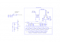
In attachement you will find the LTSpice schematic corresponding to the AD7066 speaker model with PXE sensor and the same polarization stage as used during measurement. You will also find the two curves together, the one from the measurement and the one simulated.
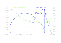
As you can see, the fitting is quite perfect up to 7kHz (far far enough) on gain and phase. To obtain that I've inserted some 2nd order filters between the cone acceleration signal and the PXE sensor acceleration input to simulate the influence of cone breakup over PXE sensor.
So now I have a very accurate model of the speaker response seen by the PXE sensor to simulate the complete behaviour with the EVE board, amplifier and feedback loop. The model is behaving as the real speaker (from motion and PXE signal point of view) so we can play with the enclosure volume we want and the feedback loop parameters we want.
The SPL response output of the model is still based on pure pistonic cone motion without breakup but it is not that I want to simulate accurately. For that the real measurements within the enclosure will be better !
In attachement you will find the LTSpice schematic corresponding to the AD7066 speaker model with PXE sensor and the same polarization stage as used during measurement. You will also find the two curves together, the one from the measurement and the one simulated.
As you can see, the fitting is quite perfect up to 7kHz (far far enough) on gain and phase. To obtain that I've inserted some 2nd order filters between the cone acceleration signal and the PXE sensor acceleration input to simulate the influence of cone breakup over PXE sensor.
So now I have a very accurate model of the speaker response seen by the PXE sensor to simulate the complete behaviour with the EVE board, amplifier and feedback loop. The model is behaving as the real speaker (from motion and PXE signal point of view) so we can play with the enclosure volume we want and the feedback loop parameters we want.
The SPL response output of the model is still based on pure pistonic cone motion without breakup but it is not that I want to simulate accurately. For that the real measurements within the enclosure will be better !
Attachments

To my best of knowledge, you are the first one to fully model piezo (or cone for that matter) breakup modes in LtSpice (I believe that is what you work with) in MFB context. In just a few weeks times you have already surpassed most of us in simming the loop. This is nothing short of spectacular. It is great a pity Stephtsf never got this far, here om DIYA at least.
If you want a somewhat similar, but visually more accessable approach you can use VituixCad for simming. VCad has the advantage you do not need to model the loudspeaker: you can directly import the measurement. Furthermore you can toggle the value of each individual component easily. Allez le MFB!
If you want a somewhat similar, but visually more accessable approach you can use VituixCad for simming. VCad has the advantage you do not need to model the loudspeaker: you can directly import the measurement. Furthermore you can toggle the value of each individual component easily. Allez le MFB!
Yes I know VituixCAD which is a powerfull tool ! I use it during acoustic tuning sessions.
From the current purpose LTSpice model is best to mix acoutic and electronic signals for the tuning of EVE board.
It should be really interesting if Chriscam could give the electrical model of Starbass sensors (parasitic capacity of PXE element, polarization resistors and JFET model). I've bought 3 of them (ClingOn) and I will equipped at least my two SEAS L26ROY. I will do the same process with them.
This is an interesting thread and has given me some ideas. I have 6 new SV12s sitting in boxes waiting for a purpose. I had another 2 running in 4 cu ft sealed boxes and the bass was the most musical I've ever heard from a dedicated 12" sub, even past 120 Hz. Most people would have crossed way lower, but this driver plays so clean up top that you could cross at 200 Hz to a 5" mid in a 3 way.
For servo control scheme, I would opt for current feedback as it tends to reduce the issues with VC inductance non-linearities. This is a big factor in reducing overall distortion at the higher frequencies past the cutoff. It will allow for better integration into the midbass region. I had a set of nearfield monitors with current feedback and was impressed with how good the midbass sounded while reaching past 30 Hz with an 8" driver + PR in a 20 L enclosure. Compared to an older ART sub which used a condenser mic for FB, it sounded much cleaner and less fussy with alignment.
For servo control scheme, I would opt for current feedback as it tends to reduce the issues with VC inductance non-linearities. This is a big factor in reducing overall distortion at the higher frequencies past the cutoff. It will allow for better integration into the midbass region. I had a set of nearfield monitors with current feedback and was impressed with how good the midbass sounded while reaching past 30 Hz with an 8" driver + PR in a 20 L enclosure. Compared to an older ART sub which used a condenser mic for FB, it sounded much cleaner and less fussy with alignment.
Dear all, I've finally finished the sound bar for my son including the Philips AD7066 ! It was a nightmare to obtain something working in closed loop and I have reduced the feedback gain to 10dB maximum to keep the system stable.
10dB is quite bad but it still give some interesting results regarding distortion measurement. The listening is impressive (for the size), the speaker follows every bass notes easily (but we have to take care about excursion).


10dB is quite bad but it still give some interesting results regarding distortion measurement. The listening is impressive (for the size), the speaker follows every bass notes easily (but we have to take care about excursion).
- Philips EVE - 10dB - OLTF.png : give the Opened Loop Transfer Function of both speakers in the system. You can see they are not behaving exactly the same.
- Philips EVE - 10dB - Left OLTF + phase.png : the detail of left Philips including the phase
- Philips EVE - OL-MFB comparison without filter.png : In blue the SPL of the Philips in closed loop, in violet in opened loop
- Philips EVE - OL-MFB comparison with filter.png : In brown the SPL in closed loop with a DSP correction to have it flat, in red in opened loop with a DSP correction to reach the same target (the correction is fare more agressive for sure)
- Philips EVE - MFB with filter -6dB distortion.png : the distortion figure in closed loop with the flat target
- Philips EVE - OL with filter -6dB distortion.png : the distortion figure in opened loop with the flat target. Notice the difference 10% at 30Hz vs 1.5% for the closed loop ! The most important reduction is on 3rd harmonic, in the meantime the 2nd stay the same or little bit above (warmer ?).
- Philips EVE - MFB with filter spectrogram.png and Philips EVE - OL with filter spectrogram.png : not relevant ? But the group delay of closed loop seems smoother ?
Wonderful measurements. Thanks for a convincing demonstration of MFB benefits.
An interesting plot is the electric drive into the drivers with and without the feedback. When the feedback is active, the driver signal is funny looking and distorted BECAUSE it is trying to correct the driver.
Sadly, the most wonderful benefit of MFB (more than FR or even low bass distortion improvement) is how great the transient attack sounds. Wish I knew how to demonstrate that benefit (other than by obvious hearing tests).
B.
My main system has two Philips 587, serviced by chris, with extended bottom end (-3dB@32Hz IIRC) and there is just no way back from MFB.
I've been "out of it" for quite a while, though. Personal life just took over for the last three years. Where oh where did the time go? 😉
Still have quite a few goodies from chris to play with. A modified Adam A7 with EVE and a sensor, my test enclosure with an MFB modified SB-Acoustics 5 incher plus passive radiator... lots of cool stuff for when I find the time.
That's something I've been pondering, too. I'd like to do some two-tone IMD measurements, that might be a cool way to show the MFB effect working. Maybe two tones between 50 and 150 hz or something in that range could work.Sadly, the most wonderful benefit of MFB (more than FR or even low bass distortion improvement) is how great the transient attack sounds. Wish I knew how to demonstrate that benefit (other than by obvious hearing tests).
I've been "out of it" for quite a while, though. Personal life just took over for the last three years. Where oh where did the time go? 😉
Still have quite a few goodies from chris to play with. A modified Adam A7 with EVE and a sensor, my test enclosure with an MFB modified SB-Acoustics 5 incher plus passive radiator... lots of cool stuff for when I find the time.
Hello Wankel 4486,
Good work!
I do, however, not fully understand what the pictures show. Closed loop is clear.
I struggle a bit with the overlay and the single Open Loop picture in green: should not these pictures, that is the purple and the green curve be identical? I see an extra pole @30Hz, where the curve should be straight. What is going on?
Also I am a bit intrigued about the max 10dB NFB: by looking at the phase, it seems you have some 5 dB extra feedbeck headroom,before you reach +145 degrees at unity gain. Can anyone ( Bolsert?) shed some light on this?
Yes the green and purple sould be the same but I've measured OLTF electrically and in open loop (for sure) so no DSP filter, while the purple was done with the microphone preparing the setup for distortion comparison with closed loop. I've put in sub high pass filter in Butterworth 48dB/oct at (or near I don't remember) 30Hz to protect the speaker. That's why there is a pole visible (also in distortion for open loop. For closed loop I think the feedback compensates a little bit).
I don't understand neither why I can't put the gain higher because it seems having a lot of phase margin. When I wanted to go higher the cone began to oscillate dangerously peak to peak or worst going to make a high frequency noise. I think the high frequency noise is linked to 2kHz accident which is maybe sharper than the figure in reality (rew smoothing ?).
I don't understand neither why I can't put the gain higher because it seems having a lot of phase margin. When I wanted to go higher the cone began to oscillate dangerously peak to peak or worst going to make a high frequency noise. I think the high frequency noise is linked to 2kHz accident which is maybe sharper than the figure in reality (rew smoothing ?).
Dear all,
I've equipped one Dayton Audio LS10-44 and two SEAS L26ROY with Piratelogic ClingOn 45° sensors.


I've performed some basic measurements (as previously with Philips AD7066 MFB) in free conditions in order to sim the sensor response with LTSpice. I've used this basic stage applied to sensor output.

See the PXE_OUT/Vspeaker sensor response I've obtained for both Dayton LS10-44 and SEAS L26ROY. The ClingOn seems very promising in term of phase margin (compared to Philips AD7066) !


I've equipped one Dayton Audio LS10-44 and two SEAS L26ROY with Piratelogic ClingOn 45° sensors.
I've performed some basic measurements (as previously with Philips AD7066 MFB) in free conditions in order to sim the sensor response with LTSpice. I've used this basic stage applied to sensor output.
See the PXE_OUT/Vspeaker sensor response I've obtained for both Dayton LS10-44 and SEAS L26ROY. The ClingOn seems very promising in term of phase margin (compared to Philips AD7066) !
Chris, I would like to sim the sensor with the speaker response in order to anticipate the EVE parameters following this schematic.

In order to have the good sensor behavior before applying parametric filters between ACCEL_CONE and ACCEL_PXE, could you please give us, following your Starbass schematic below, the values of R1 and R3 (R2=39Meg right ?) and give the reference of F1 JFET and T1 bipolar ? I've understood that ClingOn is equipped by two Murata sensors in parallel meaning 1.5nF of output capacitor.

Then we have a LTSpice model to quickly established response of the sensor depending of the speaker bby just free air measurement, playing with sensor gain (L203 inductance value), sim the cone breakup effect, by adding some parametric filters. After the speaker + sensor model can be modified with the enclosure volume and EVE board can be added to anticipate loop behavior.
In order to have the good sensor behavior before applying parametric filters between ACCEL_CONE and ACCEL_PXE, could you please give us, following your Starbass schematic below, the values of R1 and R3 (R2=39Meg right ?) and give the reference of F1 JFET and T1 bipolar ? I've understood that ClingOn is equipped by two Murata sensors in parallel meaning 1.5nF of output capacitor.
Then we have a LTSpice model to quickly established response of the sensor depending of the speaker bby just free air measurement, playing with sensor gain (L203 inductance value), sim the cone breakup effect, by adding some parametric filters. After the speaker + sensor model can be modified with the enclosure volume and EVE board can be added to anticipate loop behavior.
Be aware of the cable routing between sensor and interface board...
Cable shall be fixated to the spider.
Cable shall be fixated to the spider.
I follow Chris recommandations for ClingOn installation. The Chris schematic let the wire outing from the sensor along the cone and that all. I hope it will be fine... 🤔Be aware of the cable routing between sensor and interface board...
Cable shall be fixated to the spider.
If I recall correctly, Chris had either that SEAS model or a similar one in his lab a few years ago. He'll surely be able to tell you what works with this one.
Yes these measurement are free air.Are these measurements Free Air? The phase @LF almost looks to be good to be in-box...
What is strange is that the phase @LF is lower in my measurements than expected with simulation when I take the capacitance of Murata sensor and the resistors values from what I know with ClingOn. Both SEAS speakers are exactly the same, Dayton and SEAS sims fits quite well with measurements if I adjust some sensor parameters with exactly the same values !
So even my measurements are biased with the same trend or the ClingOn components values are not these I know.
Wonderful measurements. Thanks for a convincing demonstration of MFB benefits.
An interesting plot is the electric drive into the drivers with and without the feedback. When the feedback is active, the driver signal is funny looking and distorted BECAUSE it is trying to correct the driver.
Sadly, the most wonderful benefit of MFB (more than FR or even low bass distortion improvement) is how great the transient attack sounds. Wish I knew how to demonstrate that benefit (other than by obvious hearing tests).
B.
I think I have mentioned this before, but it is so interesting that it is worth repeating. I put a driver on the concrete floor facing upward. I played 20Hz and the membrane moved quite much, and close to X-max.
The sound of the driver was easily heard and I could point out the location of the driver in the room even if I closed my eyes.I measured the sound output with microphone (Umic ). Then I applied the feedback loop and cranked up the signal until I reached the same output at 20 Hz as before. Now I did not hear the driver. Even the fundamental 20Hz was difficult to hear. The membrane was moving and the sound pressure was clearly the same within a dB or so. But the driver was quiet... the harmonics was suppressed and high frequency content did not reveal the direction of the sound source. When people say that we can not hear a subwoofer location when it is crossed over at 80 Hz it is true and false. It is true if you have a low distortion subwoofer, but most subwoofers distorts a lot. specially those fancy ones with rubber surrounds that looks like inflated car tire inner tubes... and 2 kW power amps. Finally I have ordered Starbass accelerometers and I can crank up the feedback levels i had before (22dB) in experiments. Now it is much easier to get a robust non resonant fixation. The ACH-01 is good but has some drawbacks... I will come back with measurements in the autumn!!
The sound of the driver was easily heard and I could point out the location of the driver in the room even if I closed my eyes.I measured the sound output with microphone (Umic ). Then I applied the feedback loop and cranked up the signal until I reached the same output at 20 Hz as before. Now I did not hear the driver. Even the fundamental 20Hz was difficult to hear. The membrane was moving and the sound pressure was clearly the same within a dB or so. But the driver was quiet... the harmonics was suppressed and high frequency content did not reveal the direction of the sound source. When people say that we can not hear a subwoofer location when it is crossed over at 80 Hz it is true and false. It is true if you have a low distortion subwoofer, but most subwoofers distorts a lot. specially those fancy ones with rubber surrounds that looks like inflated car tire inner tubes... and 2 kW power amps. Finally I have ordered Starbass accelerometers and I can crank up the feedback levels i had before (22dB) in experiments. Now it is much easier to get a robust non resonant fixation. The ACH-01 is good but has some drawbacks... I will come back with measurements in the autumn!!
To be honest: I do not understand that PXE section It looks like a low pass to cut of the piezo output, possibly to kill a resonance of the accelerometer, but as such it negatively impacts phase where you do not want that to happen. The whole problem of the loopshaping is that improving phase margin in the low end tends to impact the phase margin the high end...
Remember this EVE design dates back 3 years already and I've learned a lot since then 😎 to cut short : it was an attempt to increase loop-gain by low passing the pxe signal in a 2 way design. I found that you can only do that so much until it starts affecting the FR because the pxe lpf is causing a rise in amplitude due to missing negative feedback pxe signal above lpf.
Sadly, the most wonderful benefit of MFB (more than FR or even low bass distortion improvement) is how great the transient attack sounds. Wish I knew how to demonstrate that benefit (other than by obvious hearing tests).
B.
Which perfectly outlines why I'm not doing any FB or Google ads, hearing is believing much like tasting good food.
Chriscam, could you please provide information to update the PXE sensor section according to Starbass sensors ? I think we need, parasitic capacitance of sensor, polarization resistance values, JFET model and global sensitivity in mV/G for at least one or two frequencies ?
R1=100K, R2=39M, R3=10K, F1= BF4416 T1=BC860C PXE = PKGS-00LDP1-R
Be aware of the cable routing between sensor and interface board...
Cable shall be fixated to the spider.
Correct, the coaxial cable should be mounted like below to minimize excursion stress,
In general, sorry for being unresponsive, been very busy building Grown/Up enclosures and doing R&D work.
A clever and meaningful test. Thanks....But the driver was quiet... the harmonics was suppressed and high frequency content did not reveal the direction of the sound source. When people say that we can not hear a subwoofer location when it is crossed over at 80 Hz it is true and false. It is true if you have a low distortion subwoofer, but most subwoofers distorts a lot....
The old belief of crossover favouring 80 Hz is based on lab tests locating a sound source... and maybe some of those "lab" woofers had detectable harmonics up the scale, even if the test input was pure sine wave. In domestic practice with music, 130 Hz works fine if the woofer (esp with MFB) has low harmonics and sharp Xover slopes even for a Klipschorn bass in a far corner, as I had for some decades. Maybe 200 Hz if the woofer sits centreline.
- Home
- Loudspeakers
- Subwoofers
- MFB for ACI SV12 Drivers using Piratelogic Electronics