Working on getting you the all new and improved EVE 2020.
- Adjustable accelerometer bias voltage...
What is the function?
Seems to me that simply working with the universally accessible and used (and can be bought on eBay too) ACM-01 which has an integrated circuit on the assembly, would be the natural approach for most of us... instead of the raw Star accelerometer?
B.
If I understand you correctly, first of all you are planning to correct the woofers outside the MFB loop, and then apply MFB to the (mildly?) corrected system? I suppose you then keep the most distorted part of the woofers new passband outside the loop. I.m.o. that defies the purpose of MFB. Excursion is still excursion, whether one applies MFB or not.
...my lack of fundamental understanding control theory and stability issues...
Me too. With EQ upstream to the MFB amp, the sensor still finds a deficit of 30 dB that needs at least partial correcting relative to the input signal. You can finagle the MFB amp so as to taper off correction at really low frequencies or go with modest correction, one or both of which ESL63 might be doing. But then you are adding phase and amplitude headaches to your feedback circuit.
Of course, ESL63 has been running MFB a long time, so that's proof it can be done.
B.
Post 21 you have a table.
Could you update it with the final values?
Could you update it with the final values?
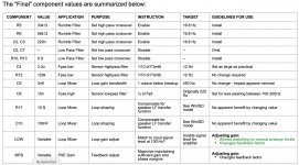
Upon review of all the analyses and trends they revealed, a table summarizing guidelines for component selection was generated.
Post 21 you have a table.
Could you update it with the final values?
I think this is what I ended up with:
Attachments
Hello rscamp,
Did you by any chance ever produce an in-box measurement of the (woofer-mounted)sensor output, and if so, could you post that file, preferably as .frd file including the phase?
Did you by any chance ever produce an in-box measurement of the (woofer-mounted)sensor output, and if so, could you post that file, preferably as .frd file including the phase?
Post 21 you have a table.
Could you update it with the final values?
Hello rscamp,
Did you by any chance ever produce an in-box measurement of the (woofer-mounted)sensor output, and if so, could you post that file, preferably as .frd file including the phase?
I don't think so. I can't seem to lay my hands on one.
Very Last Question: did you ever manage to get the system fully functioning without hum, stability issues or other quirks?
Very Last Question: did you ever manage to get the system fully functioning without hum, stability issues or other quirks?
Well, there is still a bit of hum even after adding the recommended cap at the sensor. This is unfortunate because otherwise the system performance is very good.
I've finally managed to obtain some flexible shielded cable which could well fix your hum - I'll send you a sample.Well, there is still a bit of hum even after adding the recommended cap at the sensor. This is unfortunate because otherwise the system performance is very good.
Did you manage to get your StarBass 6 equipped 10S6-4 fully functioning without hum, stability issues or other quirks yet ?Very Last Question: did you ever manage to get the system fully functioning without hum, stability issues or other quirks?
Last edited:
I've finally managed to obtain some flexible shielded cable which could well fix your hum - I'll send you a sample.
Thanks, Chris! I'll give it a try!
Just want to say  ... great thread. Super interesting and lots of super insights and contribution.
I must try this one day 😉
BR Baldin
... great thread. Super interesting and lots of super insights and contribution.I must try this one day 😉
BR Baldin

Definitly 🙂 ps, it's amplifiersJust want to say
I must try this one day 😉
BR Baldin
Page not found – SensibleAudioamlifiers/
Dear all, I prefer to continue on that old topic instead of create a new one because I think it could be a source for some others MFB beginners like me.
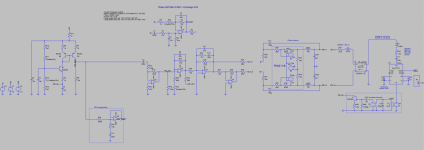
I'm trying to simulate a MFB system based on old Philips AD7066/4 MFB driver and Piratelogic EVE board from chriscam.
I've started with the impressive work from steph_tsf (whose seems not longer available on this forum) to simulate the driver and enclosure. I've added a simplified model of a class D amplifier I wanted to use (TPA3118 from a diyaudio thread). I've modelled the latest EVE board electrical schematic with LTSpice.
This thread is an amazing source, especially bolserst posts about phase margin evaluation.
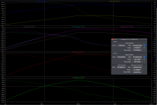
Please see the attached files. What is disturbing me is the evaluation of open loop transfer function. From the input signal (at the entry of TPA3118), voltage and current into the speaker are quite in phase (not so much delayed), then the acceleration of the membrane and so the SPL are also coherent (for a speaker), but then after PXE sensor and the others electrical filters, the phase is shifting (delayed ?).
At the end the OLTF presents a phase close to 180º at 1Hz, but -364º at 1kHz ! If I wrapped the phase, it's worst ! It doesn't follow at all the figures from the post #147 from bolserst.
I'm not use to evaluate feedback loop and phase margin, is somebody can help and explain what is going wrong or I've missed ?
I'm trying to simulate a MFB system based on old Philips AD7066/4 MFB driver and Piratelogic EVE board from chriscam.
I've started with the impressive work from steph_tsf (whose seems not longer available on this forum) to simulate the driver and enclosure. I've added a simplified model of a class D amplifier I wanted to use (TPA3118 from a diyaudio thread). I've modelled the latest EVE board electrical schematic with LTSpice.
This thread is an amazing source, especially bolserst posts about phase margin evaluation.
Please see the attached files. What is disturbing me is the evaluation of open loop transfer function. From the input signal (at the entry of TPA3118), voltage and current into the speaker are quite in phase (not so much delayed), then the acceleration of the membrane and so the SPL are also coherent (for a speaker), but then after PXE sensor and the others electrical filters, the phase is shifting (delayed ?).
At the end the OLTF presents a phase close to 180º at 1Hz, but -364º at 1kHz ! If I wrapped the phase, it's worst ! It doesn't follow at all the figures from the post #147 from bolserst.
I'm not use to evaluate feedback loop and phase margin, is somebody can help and explain what is going wrong or I've missed ?
Attachments
Last edited:
Lookup the original 22rh541 schematic where this driver was used originally, you'll find that there's some compensation in place for the accelerometers lower F3. Try increasing R48 in your simulation to 39M.
Also see the latest EVE doc for more info.
Also see the latest EVE doc for more info.
Without having a proper 2 channel measurement of the in-box accelerometer including its phase you cannot accurately sim the loop. The processsor in its most crude form is basically a leaky integrator aka a lowpass or a shelf with a very low corner frequency. That integrator or shelf is necessary to reduce the phase angle at the frequencies around and below Fbox with 90 degrees. Post 148 by Bolserst sums it more or less all up.
Many thanks for your help. I've already extensively red EVE documentation and try to understand 22RH541 documentation but my knowledges are limited on feedback systems.
I guess that my point (I can not understand) is more at high frequency. The circuit called PXE compensator in my simulation is, I think, able to lower the F3 from PXE and increase the low frequency phase margin if I plug it between PXE_RAW and C7=680nF, isn't it ?
Why I exceed by far the -180º in the upper frequency range, contrary to the post #147 and #148 ? If I understand well, an integrator will have -90ª shift at high frequency which would be worst and a shelf will have no impact at high frequency.
Sorry for my beginner questions, maybe I miss a basic knowledge of feedback. Can it be possible to have a feedback shifting more than -360ª the complete signal and in this case, the integrator is there to put the low frequency in the range of <(-360+180º) ?
To be honest: I do not understand that PXE section It looks like a low pass to cut of the piezo output, possibly to kill a resonance of the accelerometer, but as such it negatively impacts phase where you do not want that to happen. The whole problem of the loopshaping is that improving phase margin in the low end tends to impact the phase margin the high end...
- Home
- Loudspeakers
- Subwoofers
- MFB for ACI SV12 Drivers using Piratelogic Electronics