I apologize by my ignorance, but how do you separate or differentiate between two currents that flow in the same wire?
As AndrewT said, they are at different frequencies (the DC-bias is at 0 Hz).
See http://www.diyaudio.com/forums/soli...rating-class-ab-amplifier-13.html#post5098942
Although my knowledge is always limited, in the emitter of a BJT (like in any other ramp device), there only is a single component: a quiescent current/voltage plus a variable DC current/voltage caused by the signal being amplified. I still do not understand how the guy discriminates both.
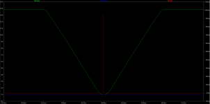
@Osvaldo, see post #142, and also consider that the measurement is taken (actually) at zero crossing.
Ahhhhhhhhhhhh, at zero crossing. I understood that you want to measure continuously every 360° of the signal applied. Now things are clearer. Thanks a lot. :-D
@Osvaldo, but not using an actual zero-crossing-detector, see http://www.diyaudio.com/forums/soli...rating-class-ab-amplifier-13.html#post5098970
...Same thing as measuring the current at zero output voltage with potential problems of current/voltage phase shift.
Not a problem (phase shift), the ballast resistors (should) have no (very little) inductance, this will make that at the ballast resistor voltage and current are always in sink 🙂 I hope.
As before, a real build of the gadget will give the 'final' answer 🙂
If the load is reactive then the current and voltage of the output will variously be out of phase (leading or lagging) and in phase from moment to moment while the music/audio is playing.
If the measurement is unresponsive to the absolute value of output voltage, then your monitoring of voltage across the upper and lower emitter resistors will be measuring current.
If the measurement is unresponsive to the absolute value of output voltage, then your monitoring of voltage across the upper and lower emitter resistors will be measuring current.
I know, but the signal is of no interest, only the bias and that one is DC. So if the bias is DC and the ballast resistors are non inductive of capacitive than I would assume that a gadget like described will make a valid measurement. As I said, lets see what happens in the real world.
A non solution is being sought for a non problem.
IF BIAS IS ADJUSTED AT IDLE, NO SIGNAL, AND THERE IS PROPER THERMAL TRACKING, THERE IS NO NEED TO MEASURE IT REAL TIME.
IF THERE IS POOR/NO THERMAL TRACKING, THEN REDESIGN THE BIAS SYSTEM UNTIL IT WORKS PROPERLY. PERIOD.
LOTS OF GOOD ENGINEERING SHOULD NOT BE WASTED TRYING TO PATCH **POOR** ENGINEERING.
Which is what this crappy thread is trying to do.
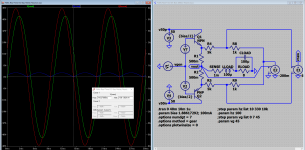
The part with red arrows (below) seems unusual; the output of a 7805 voltage regulator IC is connected to ground.
Does this mean there are two completely independent power supplies? One supply is (+30V, GND) and the other supply is a floating 15V? The 7805 regulator clamps the floating 15V supply nodes to (+10V , -5V) ?
The opamp requires a negative supply so it can reproduce the bottom half of the signal waveform, and this arrangement ensures the opamp VCC (+10V) and VEE (-5V) pins are isolated from the high current, high power yuck-noise that Q1 injects onto +30V and GND. And then C3 injects all that noise straight back into the output. Golly.
_
The only reason is to create a -15V wrt ground for the opamp. Since the regulator will maintain its output to +15 wrt ITS ground pin, connecting its output to the system gnd means ITS ground pin is at -15V wrt system ground. The mental exercise is to realize that gnd is just another name for a ref terminal and you can have several ref terminals in a system.
I remember being at the bench all exited to get this going and grabbing whatever was near to get what I needed. Doubless smarter/better ways are possible.
But it's a great way to confuse people 😎
Jan
A non solution is being sought for a non problem
Not true, but you do not like it.
IF BIAS IS ADJUSTED AT IDLE, NO SIGNAL, AND THERE IS PROPER THERMAL TRACKING, THERE IS NO NEED TO MEASURE IT REAL TIME.
Yes, so what, this thread is about measuring, not regulating (read post #1)
IF THERE IS POOR/NO THERMAL TRACKING, THEN REDESIGN THE BIAS SYSTEM UNTIL IT WORKS PROPERLY. PERIOD.
Yes, so what, this thread is about measuring, not regulating (read post #1)
LOTS OF GOOD ENGINEERING SHOULD NOT BE WASTED TRYING TO PATCH **POOR** ENGINEERING.
Yes, very true, but this thread is about measuring, not regulating (read post #1)
Which is what this crappy thread is trying to do.
Now you are insulting (after all the shouting [all upper cast]) every one that contributed to this thread, including me for starting it (the thread), please refrain from such language. If you are not willing to contribute, or even debate on technical grounds, than please refrain from commenting.
A non solution is being sought for a non problem.
IF BIAS IS ADJUSTED AT IDLE, NO SIGNAL, AND THERE IS PROPER THERMAL TRACKING, THERE IS NO NEED TO MEASURE IT REAL TIME.
IF THERE IS POOR/NO THERMAL TRACKING, THEN REDESIGN THE BIAS SYSTEM UNTIL IT WORKS PROPERLY. PERIOD.
LOTS OF GOOD ENGINEERING SHOULD NOT BE WASTED TRYING TO PATCH **POOR** ENGINEERING.
Which is what this crappy thread is trying to do.
Well sure, but how do you know there is proper thermal tracking? You need to measure it some way. That's what we are discussing.
And you can release the caps lock now, we get it 🙂
Jan
If the load is reactive then the current and voltage of the output will variously be out of phase (leading or lagging) and in phase from moment to moment while the music/audio is playing.
If the measurement is unresponsive to the absolute value of output voltage, then your monitoring of voltage across the upper and lower emitter resistors will be measuring current.
That is why I measured at current zero crossing. Obviously we are not interested in the current at voltage zero crossing as such.
I thought I made that clear in the article.
Jan
That does not follow.......................
IF BIAS IS ADJUSTED AT IDLE, NO SIGNAL, AND THERE IS PROPER THERMAL TRACKING, THERE IS NO NEED TO MEASURE IT REAL TIME...................
Both D.Self and R.Cordell have written extensively on this.
That may be a stability problem for some amplifiers, and could (I think) not be used in a production amplifier. The stability problem would prohibit a general measurement device and the relay-breaking-while-playing would be a problem in an production amplifier.
Two questions, how did the device 'see' reactive loads? and what (as a percentage) was the precision reached?
Indeed it is not meant to be included in a production device, more to satisfy my curiosity. I would expect it to be audible while playing music. But I did nor see any stability problems with the solid state load relay. Remember, you are breaking the load when the current is already almost zero.
Connecting the test stuff to the Re's requires some care with stopper R's to avoid instability though.
Reactive loads are irrelevant because I look at current zero crossing. With respect to accuracy I remember easily being able to measure fractions of a mA, repeatedly the same values.
Jan
PS Sorry for the late reply, you guys move at lightspeed!
Last edited:
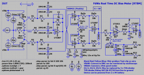
This is it, my completed version of a 'Real Time DC Bias Meter', the schema looks like buildable (I did not yet build one). Let me know what you think of it, and what may need improvement/change.
Attachments
- Status
- Not open for further replies.
- Home
- Amplifiers
- Solid State
- Measure DC-bias in a operating class AB (or A) amplifier