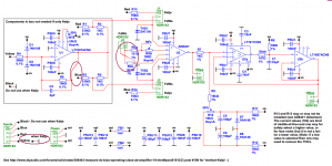
I can see green crossing over both red and yellow. That requires green to be on a different layer from red and yellow.
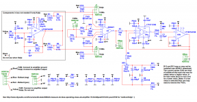
I can see red crossing over both yellow and green. That requires red to be on a different layer yellow and green.
That layout needs at least three layers.
If there is also a hidden layer then that adds up to four layers.
I can see red crossing over both yellow and green. That requires red to be on a different layer yellow and green.
That layout needs at least three layers.
If there is also a hidden layer then that adds up to four layers.
@AndrewT, see post #201 http://www.diyaudio.com/forums/soli...rating-class-ab-amplifier-21.html#post5102211
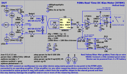
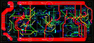
This is the complete set of drawings, from the simulation to PCB and 3D. The circuit supports the full method [FdW] and the simpeler method [Ketje], for this there are 3 jumper sets J1...J3. Maybe some footprints should be changed or I did make some mistake here or there, please let me know.
Note: FB1 and FD2 are ferrite beads (not 1uH inductors as shown in the MultiSim drawing).
Note: The board size is 45mm x 100m.
P.s. The PCB has been created from the MultiSim[white] drawing, all simulations where done in LTspice[gray], so it has been possible to make mistakes in the transcription process.
P.s. The ground plane in the PCB picture is hidden (for clarity 🙂) the layers are: top green L1 signal, 1st inner L2 signal, 2nd inner L3 ground, bottom red L4 power.
Attachments
-
FdWs Real Time DC Bias Meter; AD8421; V1.asc9.4 KB · Views: 71
-
 FdWs Real Time DC Bias Meter; AD8421; V1; PCB.PNG204.8 KB · Views: 235
 -
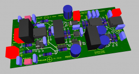 FdWs Real Time DC Bias Meter; AD8421; V1; 3D.PNG236.9 KB · Views: 222
 -
FdWs Real Time DC Bias Meter; AD8421; V1; Schema.pdf86.6 KB · Views: 70
-
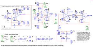 FdWs Real Time DC Bias Meter; AD8421; V1; Schema.PNG159.9 KB · Views: 242
 -
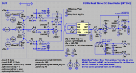 FdWs Real Time DC Bias Meter; AD8421; V1; Simulation.PNG126.6 KB · Views: 233
Last edited:
@Ketje, the 'problem' (actually stupid mistake 🙂) around J2 has been solved, the drawing around the 'red'-connector has been cleared (just a line passing over the connector, but not connected) has been updated, the texts at the signal connector has been updated.
Attachments
Last edited:
All footprints for the ceramic capacitors are now updated for mixed 2.5mm and 5mm lead spacing's.
Looks good, hope i didn't miss anything@Ketje, will you report on the changes made, see post #206

There is still place to gain on the print, two resistors and two jumpers out

Mona
Attachments
...still place, Yes, but I do like the jumpers for clarity, also, I do not like to have dual purpose resistors, in the current configuration it is possible to switch at wil.
Last edited:
Very, very interesting project and ideas that are discussed here, I keep reading with great interest. 🙂
Autobias equals sample n hold with a zero cross refresh .......
Zero cross of what?
Jan
Autobias equals sample n hold with a zero cross refresh .......
Lets see, i will be ordering some boards soon, if it works then you need to rethink your statement. For now I would say, read the thread carefully and reconsider, no zero crossing (as such, if you are pointing at the circuit being proposed here) is needed. And like Jan noted 'Of what', there is no available voltage in the amplifier to measure, you need to have a look at the actual currents (a-sink with the voltages). But, as I think we all covered that, check this (not to long thread), or wait to see what an actual build will do 🙂
There are many autobias systems in existence that do not incorporate any form of zero-crossing. Most system are temperature based servo systems, and others react to the driver stage output voltages or currents, it is also possible to average the voltage across the ballast resistors with a rc filter. Almost all these methods use the sensed result as an input to some form of servo system to regulate the output stage of the amplifier. Because these sensor-servo-loops do not make not use of a sensed-value that is exactly the same as the actual DC-bias i (in this thread) will not name it 'a measurement' but a sensor-result, estimation or representation.
To come back to the zero-crossing-detector you reference, see the paper that Jan donated and where he describes such a system, describing it's design, build and use. See also post #101 http://www.diyaudio.com/forums/soli...rating-class-ab-amplifier-11.html#post5095437
Last edited:
Here [again] a final version 🙂 please have a good look at the files posted, if you can find any problem then please report. If by tomorrow evening (my time [in about 24 hours]) no problems are reported I will order 10 boards. This new bord has a earlier reported problem fixed, the electrolytes have now 2.5mm and 5mm footprints (maximum diameter 10mm) and the trimmers are now Bourns PV37W.
Attachments
-
FdWs Real Time DC Bias Meter; AD8421; V1.asc9.4 KB · Views: 85
-
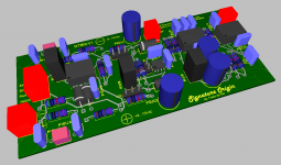 FdWs Real Time DC Bias Meter; AD8421; V1; 3D.PNG251.1 KB · Views: 331
 -
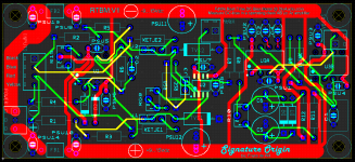 FdWs Real Time DC Bias Meter; AD8421; V1; PCB.PNG246.5 KB · Views: 322
 -
FdWs Real Time DC Bias Meter; AD8421; V1; Schema.pdf85.9 KB · Views: 94
-
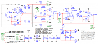 FdWs Real Time DC Bias Meter; AD8421; V1; Schema.PNG252.3 KB · Views: 338
 -
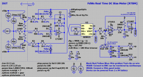 FdWs Real Time DC Bias Meter; AD8421; V1; Simulation.PNG126.6 KB · Views: 337
The cost for the PCB's is 10x11$ or 25x7$ (ex mail cost) so add you name to the next list if you want a board (or hom many).
Copy the list below and add your forum name.
PCB-buyers-list
==========
FdW 3x
Copy the list below and add your forum name.
PCB-buyers-list
==========
FdW 3x
Last edited:
I commit to purchasing two boards.
PCB-buyers-list
==========
FdW 3x
Piersma 1x
Mark Johnson 2x
PCB-buyers-list
==========
FdW 3x
Piersma 1x
Mark Johnson 2x
- Status
- Not open for further replies.
- Home
- Amplifiers
- Solid State
- Measure DC-bias in a operating class AB (or A) amplifier
