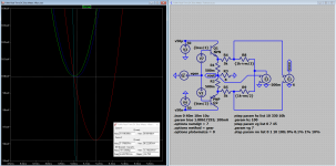
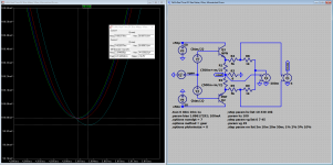
@MarcelvdG, here it is, simulated tolerances
0% All is well 🙂
0.1% Almost perfect 99.9% easy
1% The result is 96.2% and can be corrected by trimming
10% Total fail
The 100Hz signal has been measured at 5ms and 10ms (the positive max and negative max of the signal), the error where equal (and thus can be trimmed)
For the resistors R1, R2, R3, R4, R5 and R6 I do advice 0.1% precision (R5 and R6 are less critical). All other resistors should be 1%.
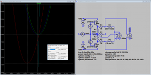
Attachments
Oh yes, i love doing that 😀No comment(s) any more 🙂 ?
What is the use of ading a common mode signal to the input of a differential amp other than to keep the input within range 😕 ,doesn't apply here, let's get rid of it 😱
Why not use the output of the amp (DUT) as reference, no deviding down, less gain needed and (very)low impedance source.A simple diff input will do.
Hope you like the striptease 🙄
Mona
Attachments

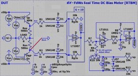
@Ketje, because it will not work 🙂 The trick that the(my) circuit is using is the fact that you can easily separate the (bulk of the) audio-signal from the signal-to-be-measured, this can be done by a simple low-voltage-tracker(U3). This is no longer possible by the circuit you propose, the attached simulation result shows the dotted line where the measurement should be made, now we need a (complex) timing generator (of some sorts) to sample the VRaw signal.
And I do have some other objections, the low input impedance (remember a 100W amplifier is running at about 90Vpp or more), the high current in the protection diodes, the high currents recycled into the PSU (this will probably kill your batteries), the extreem deep clipping on the input opamp, ... and there may be more, sorry for that, but I do like you thinking about it 🙂
P.s. you inverted VRaw 🙂
Attachments

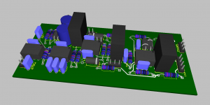
Next, I will make a MultiSim drawing so I can make a UltiBoard PCB design? For this I will be using the schema with a AD8421 INA.
Are there people interested in a PCB?
Are there people interested in a PCB?
That's the second time i do it (first time sample signal) 😡P.s. you inverted VRaw 🙂
But you took the amp's (DUT) ground as reference, i proposed the output (top of load).Makes quite a difference, the common mode is way out of range. 🙂
Mona
Last edited:
@Ketje, sorry it seems that I make mistakes to (sharing ground) 🙂
That works, but now it is impossible to share ground, so it can no longer be used to regulate that amplifier (or any other function that needs ground sharing [like PSU sharing...]).
If this is a battery operated device then this solution works nice and dandy. But if it has a mains plug then the case must be connected with the mains ground, and the amplifier also has its chassis connected to mains ground and internal ground, this creates a real danger and it will (probably under circumstances) kill your input opamp.
For sure you will not be able to use a CE-mark (in case of the device having its own mains PS) (but that is not mandatory for a diy appliance) [but I am tuned to this].
Although this is a valid option, I will stil build as proposed before 🙂 the difference in cost is not large, but it makes the device truly universal.
P.s. Did you now install and use LTspice 🙂 ?
P.p.s. Ooops, closer examination of you schematic shows you have it glued/patched together with something like paint 🙂 better get LTspice it is free and simple (my uploaded simulations run with no alterations).
Attachments

Last edited:
@Frans: if I may continue to play devil's advocate a bit: If I get it correctly, the zero xing is detected by comparing the voltage drop across the two Re's. What happens when they are of unequal resistance? Will the sampling then happen with a small residual load current running?
Jan
Jan
An interesting corollary to auto bias/active idle monitoring is the area of determining actual peak die temp in a given thermal design/operating scenario. I implemented a small circuit to break the source connection of 1 of 8 Mosfets in a normally operating class AB amplifier circuit and momentarily bias (@1 mA) the intrinsic drain source anti parallel diode for about 10 mS so as to readout in real time the instantaneous die temp. From this exercise I could watch in real time the die temp and evaluate the actual peak dissipation occurring under actual operating conditions. Quite interesting to watch in real time the peak die temp occurring on the silicon (as observed on Oscope). No substitute for actually getting accurate readings of peak junction temp in the tricky areas of bias runaway/self heating effect(s) in paralleled device output stages (with small value degeneration resistors/ current hogging scenarios) and during fault conditions with bridged tied reactive loads.
This is an interesting concept, it strikes a chord as I have been working on a way to measure instantaneous junction temperature.
In the end I ended up designing (with help of my friend Ian Hegglun) an RC-network which emulates the various thermal time constants between die and the heatsink.
I then insert Vgd and Id into a multiplexer and feed the Pd output into the thermal emulation network. Another input into the network is the heatsink actual temperature. The output of all this is the actual absolute junction temperature, real time. Ian is a wizzard at that ;-)
A practical disadvantage is that you need to design the thermal emulation network for each specific output device type. It is not very hard, you can do it in LTSpice, fiddle the network until it looks like the data sheet graphs.
Jan
Last edited:
Probably makes no different as long as the op-amp doesn't go out of it's common mode region.(Non matching Re's)
Mona
Mona
Attachments
Last edited:
@Ketje, Almost the same problems as before, no shared [true] ground (see the blue ground trace in the graph), huge voltage differences in ground (not easy to ground reference the 2, needs at the least an opamp (I think) and we get the saved opamp back), can short over shared chassis mains ground.
P.s. I will make the board configurable so that both can be build on the same board.
P.s. I will make the board configurable so that both can be build on the same board.
Attachments
@Frans: if I may continue to play devil's advocate a bit: If I get it correctly, the zero xing is detected by comparing the voltage drop across the two Re's. What happens when they are of unequal resistance? Will the sampling then happen with a small residual load current running?
Jan
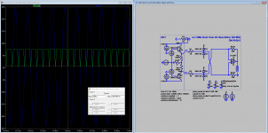
You little devil
 here it is 🙂 no worries mate the error is very small even at 10%
P.s. The 10ms error looks the same 🙂
Attachments
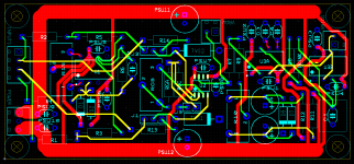
Question, does it make any sense to design a PCB, in other words when I order 10 boards (to get a reasonable price) are there then people that take one (or a few)?
You little devil
P.s. The 10ms error looks the same 🙂
Yes looks good.
Jan
This is an interesting concept, it strikes a chord as I have been working on a way to measure instantaneous junction temperature.
In the end I ended up designing (with help of my friend Ian Hegglun) an RC-network which emulates the various thermal time constants between die and the heatsink.
I then insert Vgd and Id into a multiplexer and feed the Pd output into the thermal emulation network. Another input into the network is the heatsink actual temperature. The output of all this is the actual absolute junction temperature, real time. Ian is a wizzard at that ;-)
A practical disadvantage is that you need to design the thermal emulation network for each specific output device type. It is not very hard, you can do it in LTSpice, fiddle the network until it looks like the data sheet graphs.
Jan
Hi Jan,
How do you input the heatsink actual temperature? Do you couple a temperature sensor to the heatsink and put its output voltage on the other side of the RC circuit?
I once thought of making something like that as part of a SOAR protection of an amplifier, using two BCM847 double transistors as multiplier, but I never actually built it (see post 11 of http://www.diyaudio.com/forums/soli...riable-bias-indicates-whether-works-ab-2.html). I just took a worst-case value for the heatsink temperature instead of really sensing it, though.
(By the way, the inverters at the amplifier input are not meant for soft clipping, like in Ian's designs.)
Best regards,
Marcel
Hi Jan,
How do you input the heatsink actual temperature? Do you couple a temperature sensor to the heatsink and put its output voltage on the other side of the RC circuit?
Best regards,
Marcel
Yes, I am using an LM35 with the output properly scaled, on the 'other side' of the 4RC network. The LM35 is linear in Centigrade with 0C at 0V.
Jan

- Status
- Not open for further replies.
- Home
- Amplifiers
- Solid State
- Measure DC-bias in a operating class AB (or A) amplifier