Yes measuring the bias current is really quite simple. Until you actually try it ;-)
The dynamic range between the small bias current and the actual load current is relatively high, and 'tranlating' the current info to groundside therefor hard to do with any accuracy and frequency independence, as someone noted.
Also zero xing combined with S/H alone is hard to get working reliably and accurately. I combined it with an output-side high speed solid state relay.
So I look for a zero xing, open the load relay, do the S/H, close the load relay and done. The 0-xing insures that you hit it at approximately the right point, and the load relay insures that load current is really zero so you only measure the bias current.
The system is totally autonomous and can be used under music reproduction conditions, which was one of my requirements. The very short load disconnect (some microseconds) during current 0-xing remains inaudible.
Edit: free download, for the time being ;-)
Jan
Last edited:
I will get one (schema) and check it, but this is an class-A amplifier.
It starts with a low bias which gets increased if and when needed. Not sure if this makes it a class A.
Hi Jan, thanks for the comment and the offer, I advice every one to get there and download, but more that that, go there and order those magazines/booklets.
As I am finding.
Posts #5, #44 and #84 mention that 'speed' is a problem.
That may be a stability problem for some amplifiers, and could (I think) not be used in a production amplifier. The stability problem would prohibit a general measurement device and the relay-breaking-while-playing would be a problem in an production amplifier.
Then it will be a valid research device (let me think about it 🙂)
All 🙂 go there and download 🙂
Two questions, how did the device 'see' reactive loads? and what (as a percentage) was the precision reached?
Yes measuring the bias current is really quite simple. Until you actually try it ;-)
As I am finding.
The dynamic range between the small bias current and the actual load current is relatively high, and 'tranlating' the current info to groundside therefor hard to do with any accuracy and frequency independence, as someone noted.
Posts #5, #44 and #84 mention that 'speed' is a problem.
...I combined it with an output-side high speed solid state relay.
That may be a stability problem for some amplifiers, and could (I think) not be used in a production amplifier. The stability problem would prohibit a general measurement device and the relay-breaking-while-playing would be a problem in an production amplifier.
The system is totally autonomous and can be used under music reproduction conditions...
Then it will be a valid research device (let me think about it 🙂)
Edit: free download, for the time being ;-)
All 🙂 go there and download 🙂
Two questions, how did the device 'see' reactive loads? and what (as a percentage) was the precision reached?
Last edited:
Yesterday night returning in "bondi" to home, I was thinking the case, and I arrived to a conclusion that there is nothing to measure. Re-reading the old text books, bias is only in the idle condition of an amplifier. When an input signal is injected to the amp, bias merges with signal and is delivered to the load. In fact, an amplifier doesn't amplifies nothing. Input signals modifies the quiescent condition of the idle amp transforming/converting the DC supplied to the active device (Triode, pentode, JFET, MOSFET, BJT, etc), into an AC output signal. So, no bias exists at all, it is converted to AC signals (In fact variable AC current/voltages/power) and when via a capacitor or transformer DC is remover, you get the AC clean, while the amp is operating over anc AC signal.
@Osvaldo Go to the 'free download' link in post #101 and get the article, the re-read your response.
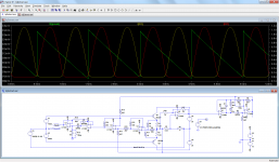
Sure, and I can even do it with "real" components, not just arbitrary spice functions.Can you show that in your simulation?
It is a plain-vanilla circuit, with every function block detailed explicitly, in a simplistic, scholar way. If you did it for real, you would use some clever tricks and end-up with half the opamps count, but at least, in this form it is easily understandable.
I have placed the ground at the output node, for convenience reasons, and the processing is carried out with a gain of 10, for a question of dynamic range.
Note that the circuit is not perfect: small offsets and disymmetries cause one of the recovered peaks to be slightly smaller than the other, but I'm sure you can perfect it 😀
Attachments
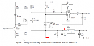
Jan Didden's Figure 12
The part with red arrows (below) seems unusual; the output of a 7805 voltage regulator IC is connected to ground.
Does this mean there are two completely independent power supplies? One supply is (+30V, GND) and the other supply is a floating 15V? The 7805 regulator clamps the floating 15V supply nodes to (+10V , -5V) ?
The opamp requires a negative supply so it can reproduce the bottom half of the signal waveform, and this arrangement ensures the opamp VCC (+10V) and VEE (-5V) pins are isolated from the high current, high power yuck-noise that Q1 injects onto +30V and GND. And then C3 injects all that noise straight back into the output. Golly.
_
Attachments
Sure, and I can even do it with "real" components, not just arbitrary spice functions...
Not bad at all, and also not to simple 🙂 I can see what you did, using the 'peak' detector functions nicely. Thanks (for the work and all).
I saw lots of stuff there, but in a quick view. In any case, it is impossible to discriminate from the emitter current, which part is bias current, which part is load current and base currents. All them are arbitrarily added inside the device, and except you can discriminate externally two of them, I see no solution readily available for your problem.
As I said, it is a verbatim, fully explicit solution: the same "algorithm" can be implemented differently, by grouping and merging function blocks differently: for example, I would certainly not use a simple absolute value detector the way I showed, but I would extract separately the |values| of Iout-Ip and Iout-In with resistor bridges and combine them later.Not bad at all, and also not to simple 🙂 I can see what you did, using the 'peak' detector functions nicely. Thanks (for the work and all).
Anyway, I think that using this Iq extractor in this limited way (just keep the zero-Xings to drive a base-spreader) is waste of resources and a missed opportunity: you can use this value as a reference for a real-time servo, to implement a non-switching scheme, where the standing current is always present and controlled, even when one device is fully ON.
Hi Jan, thanks for the comment and the offer, I advice every one to get there and download, but more that that, go there and order those magazines/booklets.
As I am finding.
Posts #5, #44 and #84 mention that 'speed' is a problem.
That may be a stability problem for some amplifiers, and could (I think) not be used in a production amplifier. The stability problem would prohibit a general measurement device and the relay-breaking-while-playing would be a problem in an production amplifier.
Then it will be a valid research device (let me think about it 🙂)
All 🙂 go there and download 🙂
Two questions, how did the device 'see' reactive loads? and what (as a percentage) was the precision reached?
It sounds to me like you are making things complicated by wanting it all at once: a circuit that can be connected to any amplifier, that accurately measures the bias current, that doesn't cause any short gaps in the output signal and that can be used for automatically controlling bias current.
If you split the functions, it gets much simpler:
For just controlling the bias current, you can use a nonlinear network rather than something with a sample and hold or with precision peak rectifiers, like in Huijsing and Tol's op-amp, Elvee's Circlophone and my BUZ10 amplifier.
For just measuring the bias current, the short gaps of Jan's circuit will usually be irrelevant.
For just listening to a conventional amplifier, you don't need any of these circuits at all.
Last edited:
The 0-xing insures that you hit it at approximately the right point, and the load relay insures that load current is really zero so you only measure the bias current.
Is timing so critical that the same cannot be achieved by muting the input?
It sounds to me like you are making things complicated by wanting it all at once...
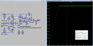
Yes and no, I just want to measure the DC bias in an operating amplifier, then (afterward) the knowledge gained can/may (as said before) be used to control amplifier bias, create a practical measuring device, ... and who knows what.

And here the simulation, looks like it will work 🙂
Attachments
Last edited:
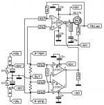
Yes because you simplify the circuit.I made a stupid inversion of the sample signalAnd here the simulation, looks like it will work 🙂

If i didn't made another error it should be like this.Makes it even simpler.
Mona
Attachments
- Status
- Not open for further replies.
- Home
- Amplifiers
- Solid State
- Measure DC-bias in a operating class AB (or A) amplifier