Why don't you just regulate it directly? Measure the voltage across the emitter degen resistors and control the OPS bias that way. If you set your values up correctly, you can decide the point at which the OPS transitions to class AB. See the sx-Amplifier, Nelson Pass also for example.
This gets complicated because the bias current is DC but its constantly changing ( from thermal effects) so it's not really DC. The trick would be to seperate the LF audio from the bias. Don't know the bias time constant, it will be different for different amps. So the filter may need to be fairly steep.
Since the bias is used to control the output transistor beta, why not use beta to control bias. Use the collector current/ base current of the output transistors with a filter. It should have little audio in it.
@Bonsai, Regulate directly? But then you need to measure firstly. You can regulate an amplifier on the basis of the average voltage across the ballast resistors (and or including the Vbe(s) of Vgs(s) of devices used) but that is not the same as measuring the bias current (or voltage across the ballast resistors). My question is not how to regulate a amplifier, yes I do know how to do that, and yes I did read Self, Cordell, the papers published by Nelson Pass and many more.
The question is, is there a known/published/patented or otherwise method to measure bias in an operating amplifier? Please point me to some solution(s) to measure the amplifier DC bias, or tell me that there is no method (still I think that Jan Didden once mentioned that he worked on a thing like that).
The question is, is there a known/published/patented or otherwise method to measure bias in an operating amplifier? Please point me to some solution(s) to measure the amplifier DC bias, or tell me that there is no method (still I think that Jan Didden once mentioned that he worked on a thing like that).
@Bonsai, this is not about regulate, it is about measure. Have you ever seen an amplifier that measures beta to do this, and how invasive is that, would it influence the audio [quality] produces? And could I build an external (hookable) measurement device to measure the bias?
Please help me find references to documented methods or tell me that it is not possible, I really would like to know that (the one or the other).
Please help me find references to documented methods or tell me that it is not possible, I really would like to know that (the one or the other).
Since the bias is used to control the output transistor beta, why not use beta to control bias. Use the collector current/ base current of the output transistors with a filter. It should have little audio in it.
Not all amplifiers are like that, actually many ar not like that. I have been a algorithm specialist for 30+ years, finding solutions is developing insight in the problem, and making measurements of the start situation, the progress and the final result. Then the final result will not be perfect but should be whit in specification.
My goat here it to establish these parameters, what have others produced, what was there cost (material, complexity etc.) why dit they do it as they did and what are the limits of such a system?
Please give me some references, we may learn some thing.
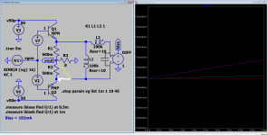
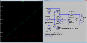
This is my tentative. Perhaps still better would be to locate in the collectors, because there the AC component is much lower. An one of the nets in each out BJT's.
O.k. 🙂 done that, but no improvement (or I did misunderstand some thing).
Attachments
Frans, sorry the bring Krell up again, but there is possibly a valuable idea there. Instead of measuring the bias through the outputs, it is measured at the pre-driver stage which always runs in class A. It is trivial to approximate the output bias from this measurement.
analog_sa, No need to be sorry 🙂 Yes I can see that and it can/may be used to regulate the amplifier, but it can not be used to get a absolute value (and absolute value would make it possible to remove all trimmers from the amplifier design) also it can not be used to create an non intrusive measurement device.
Can you point to a schematic that I can use to studie this further?
Can you point to a schematic that I can use to studie this further?
share with me your target
What i want to know is that lets suppose that we find a method to produce an accurate result Then i would like to know where and how you are going to use that .
Might be written in the post and i lost it
This is what i would like to know
How this information can be useful to anyone .
What i want to know is that lets suppose that we find a method to produce an accurate result Then i would like to know where and how you are going to use that .
Might be written in the post and i lost it
This is what i would like to know
How this information can be useful to anyone .
@east electronics, First I would like to build such a measuring device, second it would enable to build a timmer-free amplifier, and last but not least, I just want to know 🙂
The measuring device is important (to me) I do want to study amplifier bias stability under different (realistic) operating conditions. For this I would like to be able to monitor in real-time (among others) the bias behavior, set against frequency, output power, load condition(s), temperature etc.
If the measuring apparatus is simple, say up to 5 opamps a few resistors and capacitors, then one could use it to create a trimmer-free amplifier, it could even be integrated into one chip.
My dear friend i am sorry we might have a language issue but i am still not able to understand you .
Creating a trimmer free amplifier is not a question of a circuit its simply a question of proper targeting and study.
---You need to have a circuit that you like
---You need to choose the amount of bias according to a number of things
*target
*music content
*personal taste
*distortion
*harmonics
*slew rate
*probably a few more .
---Then you need to work on the thermals
---Vbe multiplier with or without a trimmer have to sense in the proper place
---Heat sink should be enough to a number of conditions
*Real life load 8R
*Real life load 4R ( if intended )
*Resistive and reactive load
*with poor wiring
*with poor speakers
*abuse /thermal tests and so on
---After you are done with that you need to go back to the circuit and check your VBE multiplier for overcompensation or under compensation in most of the above conditions .
---Then you need to recalculate all versus cost in both cases if we talk about a product in design level or in a diy construction level .
Having an "online" tool observing bias while an amplifier is in a design level want to be a final product , a diy project to be finished , or an amplifier under repair WILL NOT PROVIDE ANY ANSWERS TO THE ABOVE QUESTIONS .
Example 1
Suppose that you have a consumer amplifier under repair or investigation if you like ...Due to cost reduction the heatsink is smaller than is supposed to be , the Vbe multiplier is trigger happy , the power supply is poor, and the total resulting the bias drops dramatically , a number of distortions arise orientation from both low bias and poor power supply what will be the point of observing bias online ? Simply it is enough to see that consumer amps distort very easily if pushed .
There is a consumer logic behind this, if you like i can lay out this for you also .
Example 2
Most consumer amplifiers ( in case we talk about repair or investigating one amplifier ) feature V / VI / Zener limiters...Observing the bias on this type of circuit to learn how bias and the all amplifier will behave if pushed in real life conditions actually Cannot happen . The measured result from your tool is contaminated from the limiters so its not actually real ...Then again an "online " tool will produce NON usable results ...
It is wisher to look at the device as a total as is, or as originally calculated to observe the results of your work or your study an online tool will get you nowhere ....
My 2 cents
Last edited:
Lets see if i missed something
Lets suppose that the original question was like that :
"" I measured and listened to my amplifier and @1W plays magic with 100ma of bias @10W plays magnificent with 144 ma of bias and @100W the sound is best with 32 ma of bias "
"what will be the tool to be able to adjust my bias accurately and quickly as described above "
Answer will be
---Well actually if you know that yes it can be done but i dont think that 2 optos and one opamp will do it
While a more real answer will be
---Settle somewhere in the middle of all conditions
Notice that this will happen on a given load and a music program.Vary any of those and then data will change ....
You see choice of bias is not a given thing. For example there is oldtimers that are used to Class B sound they like the distortions of Class B There is a number of music contents that sound very nice with that type of distortion They often describe this as "character " How can you optimize the bias for them .....Give them class A amplifier and they will hate you ....
Last edited:
@east electronics, thanks for your answer, but (most of it) does not relate to the problem at hand. The problem at hand is, I want a method/device to measure class AB amplifier bias while operating.
The question was (and still is) does any one have knowledge of such a device or method, and can we share insight about this, most probably in the form of method descriptions, schematics, patents and other.
Application of such a device may be a trimmer-free amp, or a measurement device that makes it possible to actually study bias behavior, and more...
Before we could make use of such a device we first need to know how to create it, so that is the main focus (at this moment in time) of me. I want to find a answer to the question stated in post #1.
How to build such an device, and if not possible then 'why not'.
Just asking, is "idle current" for eliminating the crossover distortion between the + and - rail? Will this not need a oscilloscope to monitor?
Why to produce a device? work on it, study it when the results from this device are actually not usable This is what i don't understand .
You are asking for example a device to observe something more simple like ripple in the power supply real time , continuously, while operating at any power/condition
Ok got your result. What will you do with it ? double the filtering in the power supply , Even quadruple the filtering in the power supply After that you are in the cost reduction region you 've learned something we already know.
Likewise your tool shows that if temp in the heat sink goes above point A, Vbe multiplier senses that and drops the bias and distortions arise
What can you do with that ?
NOTHING if this is in a consumer amplifier
Yes of course you might increase size or efficiency of heatsink if in diy or design level region ....but this will be measured with a distortion analyser and not that tool you imagine ....
I sense that i am still missing something here
- Status
- Not open for further replies.
- Home
- Amplifiers
- Solid State
- Measure DC-bias in a operating class AB (or A) amplifier