@Osvaldo, No there is no isolation cap, but the simulation supplied is valid, and yes I did have a good look at the datasheet, and yes I do know that isolator (for as long as it exists).
The question is 'how to measure the DC bias', the question is not how to measure the average current in the ballast resistors, for that the opto would function nicely.
The question is 'how to measure the DC bias', the question is not how to measure the average current in the ballast resistors, for that the opto would function nicely.
Last edited:
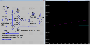
@AndrewT, Post #19 shows the same amp as post #13, the bias is functioning (see the .MEASURE directive in #13) and is 182mA. Post #19 can not show the DC bias while the (opto) isolated measurement has no ground reference.
Perhaps it a more theoretical question. Using any measurement method and giving the amp no input signal, then any voltage across the emitter resistor divided the resistor value will give the current across it.
Let me explain what would work, build a zero crossing detector and feed it with the amplifier output, then use a instrumentation amp to measure the voltage across the ballast resistors this will also reference the signal to ground. Next use a S&H to measure the value of the instrumentation amp output at the moment of zero crossing.
Simple you would think, but it is not, to take a sample at 20kHz you only have a few uSec's, timing must be impeccable, the S&H must be extremely fast (I think Jan Didden once went this way [I think], maybe Jan can jump in)
Simple you would think, but it is not, to take a sample at 20kHz you only have a few uSec's, timing must be impeccable, the S&H must be extremely fast (I think Jan Didden once went this way [I think], maybe Jan can jump in)
@Osvaldo, Yes that works, that is how it's done all the time (to adjust the amplifier bias). But, I would like to know (for sure, 100%, all the time 🙂) that it is stable under all operating conditions (some one must have done this, some ware, some time, some how).
I just want to know how to do that, and if possible use it to dynamically and automatically adjust a class-AB amplifier (and also to create such an measurement device). I'm sure that (most) amplifier builders would like to have a thing like that 🙂
I just want to know how to do that, and if possible use it to dynamically and automatically adjust a class-AB amplifier (and also to create such an measurement device). I'm sure that (most) amplifier builders would like to have a thing like that 🙂
Ahhhhh, I believe now I understood. You want to measure the bias while the amplifier is working, say, at any point of the amplifying cycle and independently of the input signal?
Thinking in the air, I believe that in a class A is simplest because the mean level of the signal is zero, then filtering out the AC signals will give the Dc component alone. But in class AB it is not true. I was also thinking in a double winded coil, wired substractibely...
Something like this:
Something like this:
Attachments
Last edited:
You state "it's there", that's just the point, it isn't.@Ketje, 'can not' is not in my vocabulary, if 'can not' then I would like to know 'why not' 🙂, it's there, so we can measure it (see post #13) the question is how? and how simple?
The bias current is only there in classA situation.
I supose with your vocabulary (or the lack of it 😛 ) you can eat food that isn't there 😕
Measuring the current at zero (voltage) crossing is fine with a resistive load.With speakers zero voltage is no garanty for zero load current.
Mona
Last edited:
@Osvaldo, class A is possible (see the #18 'Trimodal' D. Self example).
The transformer solution has the same problems as opto's it's isolated, no ground reference, and also no DC (it's a coil).
The transformer solution has the same problems as opto's it's isolated, no ground reference, and also no DC (it's a coil).
@Ketje, it is actually there, in the simulation the .MEASURE directive actually takes a measurement (182mA, see box [in the picture] 'ibiasa' and 'ibiasb')
> I supose with your vocabulary (or the lack of it ) you can eat food that isn't there
I fail to understand what that means (for now)
Edit: O.k. I see now, it refers to the lack of 'can not' 🙂 [in my vocabulary], that's what you get in a world where all is possible (maybe you need to get my CV from LinkedIn 🙂)
Last edited:
But you can use a resistive wire as the primary (In fact all wires have resistance), substitute the emitter resistor with it substract the AC by means of the counter winding rescuing the DC only, and then optoisolate it.
@Osvaldo, And then you are at the same point as in #19. Also the average DC (what you would arrive at when using a filter) does not represent the DC bias.
Referring to the sketch at #49, if you have across the emitter resistance both DC and AC currents, but if you substract variable components via transformer action, you will get the DC alone, or I'm mad?
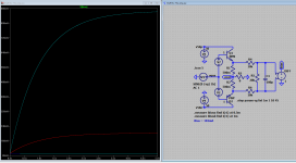
@Osvaldo, here with transformer it looks way better, but I needed to use a 100kH coil to get the shown result. I may be wrong to implement the transformer like this, any suggestions are appreciated.
The simulation shows 178mV (not 182mV) due to the fact that the 10 Ohm transformer is in parallel with the ballast resistors.
The transformer needed is also problematic, a huge bandwidth is needed, say, ...1Hz to 50kHz..., but when all fails this may be a direction to work on.
One problem is, that it will fail at low frequencies but not at DC 🙂
Attachments
Last edited:
Adding a cap between controlled device input?
This schema is used in some SMPS chips and is one inexpensive way to use DCR as the sensing resistor for current measurements.
This schema is used in some SMPS chips and is one inexpensive way to use DCR as the sensing resistor for current measurements.
- Status
- Not open for further replies.
- Home
- Amplifiers
- Solid State
- Measure DC-bias in a operating class AB (or A) amplifier