I think that with all sampled schemes, including this one, you will need to enforce a minimal sampling window: if stays open for too long, it will have a number of undesirable effects.
Either side of the zero-Xing, the measured current will be higher than the true quiescent current, and if the sample is averaged on its whole length, it will make the value higher, meaning the servo will target a value lower than expected.
The effect will be level-dependent: zero at idle conditions and maximal at full power
Another effect, at VLF's, is that the current will be modulated during the sampling window: at the beginning, the servo will think the current is much too high and attempt to reduce it, ending perhaps with a too low current at the true crossing.
This kind of behavior may introduce parasitic modulations in Xover region, a problem common to many auto-bias schemes: they cause the very type of artifacts they are supposed to cure.
Of course, this problem could always be alleviated with larger time constants, but there are practical limits to this approach.
Here, the condition of opening the sampling gate when both N and P currents are present could be replaced by In=Ip: this will ensure an always minimal, always centered sampling instant, except during true idle conditions, when it does not matter anymore.
I think that with all sampled schemes, including this one, you will need to enforce a minimal sampling window: if stays open for too long, it will have a number of undesirable effects.
This is not needed (in the shown samples, including yours) while the low-voltage-tracker will in effect take care of that. It acts as a kind of S&H with a setting time that only depends on the amount of current that the opamp can extract from the memory-capacitor. Also the speed of the opamp will influence this.
Either side of the zero-Xing, the measured current will be higher than the true quiescent current, and if the sample is averaged on its whole length, it will make the value higher, meaning the servo will target a value lower than expected. The effect will be level-dependent: zero at idle conditions and maximal at full power
This is handled by the low-voltage-tracker.
Another effect, at VLF's, is that the current will be modulated during the sampling window: at the beginning, the servo will think the current is much too high and attempt to reduce it, ending perhaps with a too low current at the true crossing. This kind of behavior may introduce parasitic modulations in Xover region, a problem common to many auto-bias schemes: they cause the very type of artifacts they are supposed to cure. Of course, this problem could always be alleviated with larger time constants, but there are practical limits to this approach.
The low-voltage-tracker and a possibly following servo could easily have a low-pass 1/frequency of 10Secs or more, for thermal regulation even 1Min would be allowable. It would (I think) be advisable to use a amplifier with an DC servo that has a time constant that must be shorter than the time constant of the DC-bias measurement so no amplified frequencies exist that conflict with the measurement system. But this thread is not about regulating amplifiers, it is just about measuring DC-bias in operating amplifiers, using the measurement method for amplifier regulation is of no concern in this thread.
Here, the condition of opening the sampling gate when both N and P currents are present could be replaced by In=Ip: this will ensure an always minimal, always centered sampling instant, except during true idle conditions, when it does not matter anymore.
Yes, but needs a more precise gating system and it is not needed while it handled by the low-voltage-tracker.
P.s. I will create a more complete simulation over the weekend.
Another idea.Not simulated, i am no good at Spice (to old)
Take samples of the current only when the two sides conduct.If the amp goes in classB the sampling is blocked.
Mona
Some ClassAB amplifiers have the ClassA level set to around -20dBW to -12dBW ref maximum power. This allows longer and many sampling periods in a piece of audio reproduction.And here the simulation, looks like it will work 🙂
But there are many ClassAB where the ClassA level is well below -30dB ref maximum power. and some will be below -60dB for the ClassA level.
That will massively shorten the period of sampling and also leave long periods between samples while the output current is above the ClassA level.
And another "but", it does allow sampling periodically during reproduction that otherwise would not be enabled.
Last edited:
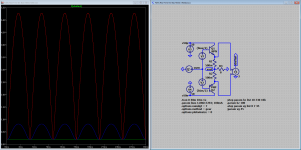
Here is one observation, it seems that the ballast resistors are in series, and for DC bias they are in series, but for 'AC-audio-currents' they are in 'anti-series'.
When the voltage across these resistors is measured this has several effects:
The audio signal is doubled in frequency
The audio signal is rectified
The bias is separated from the audio signal
The size of the voltages involved is reduced
See attached simulation and graph
When the voltage across these resistors is measured this has several effects:
The audio signal is doubled in frequency
The audio signal is rectified
The bias is separated from the audio signal
The size of the voltages involved is reduced
See attached simulation and graph
Attachments
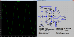
The signal generated by the amplifier under test needs to be truncated, in the previous simulation the output voltages swings from +45V to -45V, for a practical measuring device (using opamps) an voltage swing of +15V to -15V would be better. This is easy accomplished using a voltage divider at the measurement device input.
This leaves the problem of measuring precision, the smaller the difference between the input signal-to-be-measured and the signal-to-be-ignored, the easier it is to make a precise measurement.
The simulation attached here uses an inverting amplifier to subtract the amplifier output from the signal 'VSig...' to be measured, it also uses a input voltage divider to make the signal from the amplifier opamp-friendly.
The graph shows that the maximum input voltage swing changes from +-7.5V to +-500mV (the first after truncation, the second after truncation and subtraction).
Attachments
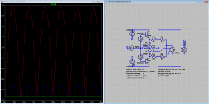
The final step, preparing the measurement source signal, is to get the difference between the VSig+ and VSig- signals, this stage can also be used to adjust the signal for the truncation that was done, so we need a bit of gain.
It is now easily seen what the effect is of the audio-signal-rectification mentioned earlier, due to this effect the audio signal is always positive, while the DC bias is also always positive, the resulting signal has the audio-signal on top of the DC-bias, it is simply a matter of detecting the lowest points in this (VRaw) signal to extract a value for DC-bias (in the simulated situation 100mA [equating 100mV across the ballast resistors])
It is now easily seen what the effect is of the audio-signal-rectification mentioned earlier, due to this effect the audio signal is always positive, while the DC bias is also always positive, the resulting signal has the audio-signal on top of the DC-bias, it is simply a matter of detecting the lowest points in this (VRaw) signal to extract a value for DC-bias (in the simulated situation 100mA [equating 100mV across the ballast resistors])
Attachments
I thought you wanted to keep it universal. The assumption that the sum of the voltages across the resistor is at its smallest when you cross the quiescent point is not necessarily correct when you measure a non-switching class B amplifier.
@MarcelvdG, why not show me? 🙂 And how universal is 'universal' (the thread (I) always stated the this should be for class AB (or class A) amplifiers)? Also class B amplifiers, and amplifiers with a shifting bias do not have a DC-bias (it is kind-of-a AC-bias).
Last edited:
It depends on the implemented control law, but actually I think I'm mistaken. Most if not all practical control laws will have the minimum sum voltage at the quiescent point.
@MarcelvgG, thanks, that clears it 🙂 I would call this residual (minimum sum) the DC-bias and that would be measured.
Last edited:
Also class B amplifiers, and amplifiers with a shifting bias do not have a DC-bias (it is kind-of-a AC-bias).
There is always some confusion about whether amplifiers with no bias at all should be called class B or class C. For the record, when I wrote non-switching class B in post 127, I meant an amplifier that does have some DC bias current. In any case, it's irrelevant because the rest of the post was wrong anyway.
Is to be expected if you take the inverted signal from an inverted source.The audio signal is doubled in frequency
The audio signal is rectified
Only as long as there is current in the two resistances.If not there is no bias only audio.The bias is separated from the audio signal
Same thing as measuring the current at zero output voltage with potential problems of current/voltage phase shift.It is now easily seen what the effect is of the audio-signal-rectification mentioned earlier, due to this effect the audio signal is always positive, while the DC bias is also always positive, the resulting signal has the audio-signal on top of the DC-bias, it is simply a matter of detecting the lowest points in this (VRaw) signal to extract a value for DC-bias (in the simulated situation 100mA [equating 100mV across the ballast resistors])
Another problem, the bias voltage between bases and drop over emitter resistances isn't the same.There is the non-linear behavior of the b-e junction of the output transistors.
Mona
There is always some confusion about whether amplifiers with no bias at all should be called class B or class C. For the record, when I wrote non-switching class B in post 127, I meant an amplifier that does have some DC bias current. In any case, it's irrelevant because the rest of the post was wrong anyway.
But we can agree that this is not influencing the proposed measuring method/system?
Last edited:
Is to be expected if you take the inverted signal from an inverted source.
Yes, but it was stated as an observation 🙂 and it is helpful to think about it (to understand the measuring method I propose).
Only as long as there is current in the two resistances. If not there is no bias only audio.
Yes, and if there is no bias then [obviously] it will not be measured. 🙂
Same thing as measuring the current at zero output voltage with potential problems of current/voltage phase shift.
Yes, lets see what happens if we actually build a device.
Another problem, the bias voltage between bases and drop over emitter resistances isn't the same.There is the non-linear behavior of the b-e junction of the output transistors.
Yes, but the Vbe voltages are not of interest for this measuring method, only the currents in the ballast resistors (equals Ie of the output devices).
Last edited:
Shure, but you use a fixed V2 + V7 for the bias.And that is not what you find at the emitters.Yes, but the Vbe voltages are not of interest for this measuring method, only the currents in the ballast resistors (equals Ie of the output devices).
Mona
Shure, but you use a fixed V2 + V7 for the bias.And that is not what you find at the emitters.
Mona
Yes? but what is the argument here? Or what do I fail to see?
I want to measure the current in the ballast resistors (where current is (V(R1)+V(R2))/(R(R1)+R(R2)), so for determining the current I assume that R(R1) and R(R2) are known), I'm not interested in Vbe's (e.g. V2 and/or V7). I do know that this is not a 'real' amplifier, it is a simple abstraction of an AB amplifier, just to be able to demonstrate/simulate the measuring method.
Last edited:
But we can agree that this is not influencing the proposed measuring method/system?
Yes, absolutely.
Aha,but in a real amp the bias is set with V2+V7 and the bias current in the output stage changes with the level of the output current.Yes? but what is the argument here? Or what do I fail to see?
I do know that this is not a 'real' amplifier,
Mona
@Ketje, so now we are on the same page 🙂 you (or I) build your (my) 'real' amplifier, then connect the DC-bias-measurement-gadget (if ever one exists), turn on the power, turn on the music (now we can listen to music while adjusting the DC-bias), and then you use the bias-adjustment-potentiometer of that amplifier to adjust the bias.
Or we use a servo to compare the measured DC-bias and with a fixed reference, then we use the output of the servo to adjust the bias-generator. The fixed reference is independent of the Vbe's involved.
Or... maybe we can think of some other purpose for this method/device/gadget 🙂
So, you see, all problems solved (except for building the DC-bias-measurement-gadget).
Last edited:
I apologize by my ignorance, but how do you separate or differentiate between two currents that flow in the same wire?
- Status
- Not open for further replies.
- Home
- Amplifiers
- Solid State
- Measure DC-bias in a operating class AB (or A) amplifier