Jan Didden wrote an article about bias stability in conventional amplifiers in Linear Audio volume 9. I don't remember by heart how he measured it, and I have no access to LA volume 9 at the moment.
If you just want to make a trimmer-free amplifier with controlled bias current, you can use the trick Johan H. Huijsing and Frans Tol came up with in 1976:
-Sense the currents through the output devices
-Put (scaled copies of) them into a non-linear network that acts as a smooth approximation to a minimum selector
-Compare the output of the network with a set value
-Make a feedback loop that increases or decreases the current through both output devices depending on the outcome of the previous step
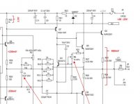
An example of this technique is the cheap little Circlophone thread on this forum. Another one is my circuit from 1994 (published in Electronics World in February 1996), that allowed me to use cheap BUZ10 MOSFETs in an adjustment-free non-switching class-AB amplifier, see the attachment. Other examples are the Linear Technology LT1166 and http://www.data-odyssey.nl/AutoBias.html
By the way, when I tested and debugged my circuit back in 1994, I simply grounded neither the amplifier nor the CD player that provided the test signal, and connected a two-channel oscilloscope with its ground to the midpoint between the 0.4 ohm resistors, with channel 1 to the upper resistor and channel 2 to the lower resistor. Press the invert button of channel 2 and you know that the graphs cross at 0.4 ohm times the quiescent current. It also shows the minimum current quite clearly, even when the test signal is music.
If you just want to make a trimmer-free amplifier with controlled bias current, you can use the trick Johan H. Huijsing and Frans Tol came up with in 1976:
-Sense the currents through the output devices
-Put (scaled copies of) them into a non-linear network that acts as a smooth approximation to a minimum selector
-Compare the output of the network with a set value
-Make a feedback loop that increases or decreases the current through both output devices depending on the outcome of the previous step
An example of this technique is the cheap little Circlophone thread on this forum. Another one is my circuit from 1994 (published in Electronics World in February 1996), that allowed me to use cheap BUZ10 MOSFETs in an adjustment-free non-switching class-AB amplifier, see the attachment. Other examples are the Linear Technology LT1166 and http://www.data-odyssey.nl/AutoBias.html
By the way, when I tested and debugged my circuit back in 1994, I simply grounded neither the amplifier nor the CD player that provided the test signal, and connected a two-channel oscilloscope with its ground to the midpoint between the 0.4 ohm resistors, with channel 1 to the upper resistor and channel 2 to the lower resistor. Press the invert button of channel 2 and you know that the graphs cross at 0.4 ohm times the quiescent current. It also shows the minimum current quite clearly, even when the test signal is music.
Attachments
Last edited:
Take a moment to analyze why Nelson Pass might choose C3 = 3.3 millifarads in the optical feedback autobias circuit of his M2 amplifier. If you read his comments in the M2 thread, he fully expects people to run ultra low impedance loads while playing LOUD, so the output stage exits class A and operates class B some of the time.
The worst case pessimistic assumption is that the transformer presents an impedance of ZERO ohms to the bottom plate of C3. Then the time constant of the top plate is (47K x 3.3mF) = 155 seconds. Why did he do that? Why am I mentioning it here?
_
The worst case pessimistic assumption is that the transformer presents an impedance of ZERO ohms to the bottom plate of C3. Then the time constant of the top plate is (47K x 3.3mF) = 155 seconds. Why did he do that? Why am I mentioning it here?
_
Attachments
Here's how I do it. Q3 is the bias regulator which directly measures the current across the two emitter degen resistors. On a 1.4A standing current, the bias variability cold to hot is c. 40mA.
Attachments
Last edited:
I think that there must be a way to do what you want, it´s not physically impossible by any means, but it *almost* amounts to that on practical grounds.
Basic stumbling block is that we call "bias" is actually *idle current with no signal applied* ... do we agree on that?
Just in case: if not, stop reading .
Still here? Ok, let´s go on then:
First problem is that you want to measure it real time, even with signal applied. Is that so?
Second problem is that the normal way to measure it measuring voltage drop across a resistor in series with power transistors; ballast emitter is a "free" one because it´s there anyway, so measuring such voltage, at idle, with a multimeter, is a popular solution ..... only that you don´t want a manual measurement, nor manual adjustment, and with signal present.
You´re a complicated guy, did anybody tell you that ? 😛
We can also add a series resistor anywhere in the current path and measure that drop.
Third problem is that voltage drop is not only that caused by idle current BUT by current into the load, which can be:
* up to 1000X larger 😱
* any frequency, in principle between 20 Hz and 20kHz but may extend beyond that.
* any waveform
* since load is reactive and in an unpredictable way (measurement should not depend on which speaker you use) current through sampling resistors will track whatever the load impedance does.
* I must certainly be ignoring some other problem 🙁
considering all that, sampling voltage drop across a resistor and *extracting* useful information from there IS possible, but probably unjustified in a simple consumer product.
It´s definitely justified extracting useful data deeply buried in noise and all kinds of interference from, say, data transmitted from a Mars or Jupiter probe or whatever, but ... in a cheap consumer product?
As I said before, it´s physically possible but hardly justifying the brains, time and money involved.
There are some ways to "cheat" of course, but they do not meet all of your requirements.
a) the usual way: you measure and adjust at idle, test amp at different power levels so different heatsink temperature, also vary ambient temperature, until you are satisfied temperature compensation tracks and corrects well, and then you do not "need" to measure real time 😉
Not surprisingly, it´s the most popular solution 😀
b) what I would do: detect presence of audio and measure only during silence ... worst case between songs (unless it´s DJ duty 😉 )
Store that value , compensate according to it, you will (hopefully) be updating every few minutes; given typical mass and time constants of heat sinks, that *should* be acceptable.
Of course, it does not meet your "continuous real time" constraint.
c) what was suggested earlier: measure during "zero crossing" .
Similar to (b) but updated at much higher rate.
possible in theory but any normal signal spends "zero" time at the actual zero crossing point ..... think a little about that.
Plus what was also correctly mentioned: complex reactive loads will complicate measurements. Big time.
d) this one might meet your requirements: a substractive method, possible in theory: you might accurately measure voltage drop across ballast resistors, which carry both idle and load current, also accurately measure voltage drop across a sampling resistor which is in series with load but not the transistors , and substract them.
Difference "should" be idle current at any signal level.
The main problem is extracting that data with any precision; then referencing it to ground or using it to control some bias element is compratively a lesser problem.
Hope you are aware of what you are asking 😎
Last edited:
Just asking, is "idle current" for eliminating the crossover distortion between the + and - rail? Will this not need a oscilloscope to monitor?
Yes (and no) 🙂 Post #13 shows how to measure it with an oscilloscope, if possible (to use a oscilloscope) it may be the easiest method. The oscilloscope method is not very useful for a automated bias circuit or logging.
Why to produce a device? work on it, study it ...
@east electronics, thanks for your answer, but (most of it) does not relate to the problem at hand. The problem at hand is, I want a method/device to measure class AB amplifier bias while operating.
Read post #1 (that's the question) I can see that you are not interested in a method/device like this.
Jan Didden wrote an article about bias stability in conventional amplifiers in Linear Audio volume 9. I don't remember by heart how he measured it, and I have no access to LA volume 9 at the moment.
If you just want to make a trimmer-free amplifier with controlled bias current, you can use the trick ...
Thanks, found the 'Jan Didden' article. This is way more complicated then I would have thought 🙂 but I need to study it further, one problem is that the Zero-crossing-detector and S&H need to be extremely fast, I am almost sure that such a device will not operate at 10kHz. Maybe Jan will be so friendly to report on that (here).
The goal is not just to build a trimmer free amplifier, if possible (a simple measurement method/device) then (as stated before) one of the purposed could/would be to do this. My main goal is just to measure, and when this is possible (and implemented) I will have a look at application possibilities.
Attachments
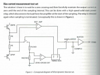
It is simply a matter of applying Kirchhoff's current law: the output node has three converging currents: current from the positive device, the negative device and the output.
The sum of Ip and In contains the output current, of course, but also twice the instantaneous quiescent current (the "shoot-through" component common to both).
This means that all you have to do is a sum, and a subtraction of the output current's absolute value (because of the rectifying effect of the class B OP).
See example below: the extraction circuitry should preferably be referenced to the output node, as all the voltages representative of the currents are also referenced there: if you try to translate these small voltages to the ground or the rails, any inaccuracy will ruin the process (the operations need to be accurate, since a big bad subtraction is involved)
Attachments
Take a moment to analyze why Nelson Pass might choose C3 = 3.3 millifarads ...
Thanks Mark 🙂 my answer would be, because he knows/thinks that using a real/true measurement method/device would be overkill/expensive/complicated/(and more), maybe he would like to give his own opinion on this (here in this thread).
Edmond Stuart published an EWW article over a decade ago for an auto-bias system. Its featured on his website - Home
If I were going to measure the bias I'd probably embed a 50MHz Cortex M3 with on-chip ADCs in the bias spreader as nowadays such chips are available that draw under 20mA at 3V or so. Opto-couple an RS232 line to it for comms.
If I were going to measure the bias I'd probably embed a 50MHz Cortex M3 with on-chip ADCs in the bias spreader as nowadays such chips are available that draw under 20mA at 3V or so. Opto-couple an RS232 line to it for comms.
Last edited:
Here's how I do it. Q3 is the bias regulator which directly measures the current across the two emitter degen resistors. On a 1.4A standing current, the bias variability cold to hot is c. 40mA.
Thanks Bonsai, an averaged measurement will function for bias regulation of an amplifier, it will nut function as a bias measurement (with any precision). One possibility of an real time method/device, as I am looking for, would be to measure and verify the bias method you are using.
The method you are using needs further study, although it is not useful as an accurate measurement method, it is interesting as an amplifier regulation method.
D'Agostino patent 5,331,291
This is a method to regulate the class-A current in accordance with load, actually very clever, this is easy (actually it is very complicated) as shown earlier in this thread, it is feasible to measure the bias while the amplifier is in class A to do so while the amplifier is in class AB (e.g. the output (or I(e)) currents are larger than the bias) is an other problem.
Patent US5331291 - Circuit and method for adjusting the bias of an amplifier based upon load ... - Google Patents
http://www.diyaudio.com/forums/soli...ained-plateau-design-some-thoughts-print.html
http://www.krellonline.com/pdf/FPB_man_S.pdf
http://krellonline.com/downloads/Phantom Owners Reference.pdf
I will check these, but they are not (I think) going to lead to a 'general' measurement method/device.
the circuit of FPB200
I will get one (schema) and check it, but this is an class-A amplifier.
http://krellonline.com/assets/support/FPB_ORIGINAL_SERIES_MANUAL_V982.pdf
For almost any amplifier bar one using lateral MOSFET outputs with only a trimmer to set bias, the relationship between bias voltage and standing current is simple, one depends on the other. There is a lag, but it is still fairly valid.
Measuring the total bias voltage should give you a very good estimate of the standing current, if the bias spreader is properly implemented. Obviously this does not cover fault conditions but I don't think that's what you were asking.
For a given amplifier it would be possible to plot various standing currents for various values of bias voltages. These would usually be quite consistent (again, given competent amp design).
Obviously if you're looking for closer measurements you will need specific devices - the Sanken transistors with on-die diodes, for example, in the output stage. Once the amplifier is under load and conducting, the whole concept of idle current is out of the window (it simply ceases to exist) so you can't measure it any more. I think that is what Mona was trying to say - can't eat food that isn't there. Once the amp isn't idling, there is no idle current.
It is simply a matter of applying Kirchhoff's current law ...
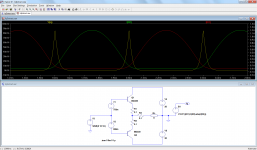
Thanks Elvee, Yes and no, the current that I want to measure is the one flowing at the moment that the currents in R1 and R2 are equal, this is true for the exact moment 1.5ms, 2ms, 2.5ms ... (in your simulation). It seems that the best (but complicated) idea (until now) has been using a zero-crossing-detector and S&H, I'm really hoping that Jan Didden will comment on that one.
If it is/was possible to just make an application of Kirchhoff's law, then it should be possible to create a/some formula in that simulation witch would calculate the bias from the given (in the simulation) currents and voltages (try it 🙂).
There is no advantage in identifying zero voltage crossing.You state "it's there", that's just the point, it isn't.
The bias current is only there in classA situation.
I supose with your vocabulary (or the lack of it 😛 ) you can eat food that isn't there 😕
Measuring the current at zero (voltage) crossing is fine with a resistive load.With speakers zero voltage is no garanty for zero load current.
Mona
It has to be zero current crossing to exclude output CURRENT from the currents passing through the emitter resistors.
For almost any amplifier bar one using lateral MOSFET outputs ...
The point is, I am looking for a known/documented method/device/patent to measure DC bias in a operating/functioning amplifier at any level and frequency. Any hint at an idea/patent or otherwise will be appreciated.
There is no advantage in identifying zero voltage crossing.
It has to be zero current crossing to exclude output CURRENT from the currents passing through the emitter resistors.
Yes
You just need to add a peak detector downstream of the extracted signal.Thanks Elvee, Yes and no, the current that I want to measure is the one flowing at the moment that the currents in R1 and R2 are equal, this is true for the exact moment 1.5ms, 2ms, 2.5ms ... (in your simulation). It seems that the best (but complicated) idea (until now) has been using a zero-crossing-detector and S&H, I'm really hoping that Jan Didden will comment on that one.
The advantage over a sample-hold is that it does not need the critical synchronization to the exact instant of the zero crossing
@JMFahay, Thanks, you are describing (most) of the challenges ahead, this should not stop me/us (would the Americans ever have been gone to the moon?) it should encourage me/us 🙂
Yes (make it so [JLP]) 🙂
Yes.
Yes.
Yes.
All true, reactivity of the load may be the biggest problem, and I am nut sure if it is possible to 'compensate' for that. Maybe Jan Didden (having build a device) can give some information on this issue.
That will depend on the complexity/cost of the solution (for now it does not seem that simple/cheap solution is possible)
Maybe 🙂 but the learning experience may be worth it(some) 🙂
To much of a "cheat" 🙂
Needs further investigation, would be good enough for bias measurement, not so good for a measurement system to study the bias behavior.
Yes, needs work, and [again] maybe Jan Didden can say something about this one.
Seems not to be possible without modifying the amplifier, that would rule out a (general purpose) measurement device. Also I have not found a way to do this in simulation (that would be the first stop for such a device).
Yes, so first 'see if an method/device is possible. One would think that I am not the first one to ask this, about 80years of amplifiers must have brought someone to the idea to measure this. Where are those methods/devices and patents .
Very 😎
Thanks for the detailed thoughts.
I think that there must be a way to do what you want, it´s not physically impossible by any means, but it *almost* amounts to that on practical grounds.
Yes (make it so [JLP]) 🙂
Basic stumbling block is that we call "bias" is actually *idle current with no signal applied* ... do we agree on that?
Yes.
First problem is that you want to measure it real time, even with signal applied. Is that so?
Yes.
Second problem is that the normal way to measure it measuring voltage drop across a resistor in series with power transistors; ballast emitter is a "free" one because it´s there anyway, so measuring such voltage, at idle, with a multimeter, is a popular solution ..... only that you don´t want a manual measurement, nor manual adjustment, and with signal present.
You´re a complicated guy, did anybody tell you that ? 😛 We can also add a series resistor anywhere in the current path and measure that drop.
Yes.
Third problem is that voltage drop is not only that caused by idle current BUT by current into the load, which can be:..
All true, reactivity of the load may be the biggest problem, and I am nut sure if it is possible to 'compensate' for that. Maybe Jan Didden (having build a device) can give some information on this issue.
considering all that, sampling voltage drop across a resistor and *extracting* useful information from there IS possible, but probably unjustified in a simple consumer product.
That will depend on the complexity/cost of the solution (for now it does not seem that simple/cheap solution is possible)
As I said before, it´s physically possible but hardly justifying the brains, time and money involved.
Maybe 🙂 but the learning experience may be worth it(some) 🙂
There are some ways to "cheat" of course, but they do not meet all of your requirements.
a) the usual way:
To much of a "cheat" 🙂
b) what I would do:
Needs further investigation, would be good enough for bias measurement, not so good for a measurement system to study the bias behavior.
c) what was suggested earlier:
Yes, needs work, and [again] maybe Jan Didden can say something about this one.
d) this one might meet your requirements:
Seems not to be possible without modifying the amplifier, that would rule out a (general purpose) measurement device. Also I have not found a way to do this in simulation (that would be the first stop for such a device).
The main problem is extracting that data with any precision; then referencing it to ground or using it to control some bias element is compratively a lesser problem.
Yes, so first 'see if an method/device is possible. One would think that I am not the first one to ask this, about 80years of amplifiers must have brought someone to the idea to measure this. Where are those methods/devices and patents .
Hope you are aware of what you are asking 😎
Very 😎
Thanks for the detailed thoughts.
You just need to add a peak detector downstream of the extracted signal.
The advantage over a sample-hold is that it does not need the critical synchronization to the exact instant of the zero crossing
Can you show that in your simulation?
- Status
- Not open for further replies.
- Home
- Amplifiers
- Solid State
- Measure DC-bias in a operating class AB (or A) amplifier