When adjusted correctly, you will have to measure the Power again.Hi Hans, thanks for your help! Before I had measured from the bottom (motherboard), now I checked again from the black caps and similarly I have 54.4V and -55.2. I will keep going down with the pot then to see if I can reach 100mV on the DC offset, currently at 1.25V.
When still 46Watt, the most likely cause is a broken soft start circuit.
We will then have to disable this circuit by taking out one leg from two diodes.
But first I'll wait what you report after having adjusted the +/- supply voltages to within 100mV.
Hans
That protection circuit is on resp. the AP-3 and on the AP-5 board.Dear Hans,
Oh, I didn’t know there was a monitor on the regulated rails voltage differential.
I didn’t see that on the protection circuit. Maybe I didn’t look hard enough
Look at posting #106.
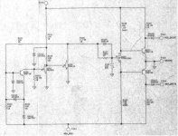
The two inputs at the left, here called resp. Y++ and Y--, are shortened by the soft start circuit preventing any current to flow in the end stage and thereby preventing a plop in the speaker at switch on and switch off.
But when broken, you have no bias either after start up.
Hans
Thank you. Learned something new. So it wasn’t in the RP3 board. I didn’t study too much in depth on the AP5 board. Fortunately I did not have that problem while working on my case. Well if it did happen, I would have to study the AP5 board more in depth then and maybe found what you described or not. 😝
Here is the soft start circuit on the AP-5 board.Well if it did happen, I would have to study the AP5 board more in depth then and maybe found what you described or not. 😝
Hans
Attachments
So, after about 15x pot turns it got the DC offset down to 127mV. It won't go further than that, for both units is exactly the same. Wattage hasn't changed much, so I guess I have a broken soft start. 🤔 Any idea of what could cause this? What's the next step with the diodes on AP-3?
Dear Hans,
Thank you for sharing and pointing out the circuit. Even if I had traced it out it would have stumped me. I probably clild understood the mosfet shunting out the base current to the output transistors but the function of The left side of the circuit would have puzzled me 🤔
Thanks again. 👍. Good job.
Good to know there is a guru out there I can rely on if I have to troubleshoot another ML amp in future.
😊
This is definitely what Hans can help. I would be learning too. 😊So, after about 15x pot turns it got the DC offset down to 127mV. It won't go further than that, for both units is exactly the same. Wattage hasn't changed much, so I guess I have a broken soft start. 🤔 Any idea of what could cause this? What's the next step with the diodes on AP-3?
The next step is to disable the soft start by interupting the signal to the two diodes.So, after about 15x pot turns it got the DC offset down to 127mV. It won't go further than that, for both units is exactly the same. Wattage hasn't changed much, so I guess I have a broken soft start. 🤔 Any idea of what could cause this? What's the next step with the diodes on AP-3?
See in the image below the two diodes accentuated in red.
Take out the whole diodes or at least one leg.
Alternative you can cut one leg and replace the diodes at a later stage by a new one.
Hans
Attachments
When taking out the diodes does not help to get the end stage biased, the next step will be to check a zener on the motherboard.
This zener is in parallel to the soft start circuit and serves to limit the maximum bias current.
But when short circuited it will also prevent the output stage to come into action.
Waiting for your feedback.
Hans
This zener is in parallel to the soft start circuit and serves to limit the maximum bias current.
But when short circuited it will also prevent the output stage to come into action.
Waiting for your feedback.
Hans
Thanks Hans. I cut the diode legs, but now the amp trips. I will try to find the zener you mentioned and check if there is a short. Unfortunately I'm going away soon and will be back on Monday. Thanks a lot for helping out.
Just one more thing, the amp (with the diodes on) does output audio, but it's weak and gets distorted as I increase the input level. I didn't notice there was an issue at first as I'm using a small speaker to test, so I thought it was normal. But audio passes through and gets amplified to a certain level, and the relay is triggered and the unit lights up when switched on. Could it still be a soft start issue? And I replaced the 9000uF with 10 000uF, that doesn't make much difference right?
You have cut both diodes, true ?
That the Amp now trips is a prove of the malfunction of the soft start.
But because you have turned the offset voltage potmeter, the amp is now outside the allowed offset window.
That makes another safe guard circuit to trip the amp because offset is too large.
So disable this safeguard as in the image below by shorting a resistor.
Now switch on the amp but without a load at the speaker output and bring the offset
to zero volt.
Hans
Attachments
Yes the amp will still produce music also without bias, but with a large distortion because jumping all the time from +1.4V to -1.4V where no output is possible but somehow corrected by feedback.Just one more thing, the amp (with the diodes on) does output audio, but it's weak and gets distorted as I increase the input level. I didn't notice there was an issue at first as I'm using a small speaker to test, so I thought it was normal. But audio passes through and gets amplified to a certain level, and the relay is triggered and the unit lights up when switched on. Could it still be a soft start issue? And I replaced the 9000uF with 10 000uF, that doesn't make much difference right?
So far all signs are pointing in the direction of a broken soft start circuit.
Hans
Dear Hans, your advice of lifting the diodes and shorting the resistor, which components are they in relation to the circuit of the soft start that you shared? Thank you.
Hi, excuse me but I'm always a bit confused about Chinese names.|
Is your first name Lim or is it KweeSong ?
Anyhow, to answer your questions.
The soft start circuit on the AP-5 board in #125 is not the same as on the AP-3 board.
But in both cases, two diodes couple to the output stage as shown in #106, thereby making a short between the two points that I called Y++ and Y-- during start up and at shut down.
Mark Levinson calls these points Pos_Drive and Neg_Drive as I found out later, but at the time I did my reverse engineering I had no documentation at all and had to select my own names.
By shorting those two point to ground, the output stage is no longer biased and current through all transistors in the output stage (fitted to the 4 big heatsinks) is zero.
The two diodes on the AP-5 are called CR106 and CR107 and on the AP-3 board D403 and D404.
See first Image below.
So when lifting these diodes, the soft start function is completely disabled.
Also notice that when the +55V and the -55V are not within 100mV in absolute value, that when the Mosfet Q103 closes and thereby shorts the bases of the two transistors together, the two 10K resistors will have their junction voltage at halfway the positive and negative voltage.
But since both emitters are still connected to ground, one of the transistors will start drawing current when the positive and the negative supply are not equal.
This leaking current will cause distortion.
Now the offset pot won't do anything when the soft start circuit doesn't release the short-circuit.
So now with the disabled soft start by lifting diodes, the output stage will start conducting current, but when the offset pot has been turned quite a bit, a large offset voltage may appear at the output.
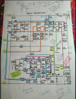
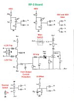
Now the RP-3 comes into action, where several voltages are monitored, the +/-80V, the +/-55V and also the offset voltage at the LS output.
And finally three thermal switches have to be closed and no overload at the LS output has to be the case.
In all those cases when something is not correct, a Thyristor will be triggered that will cause the Main switch on the Amp's front side to trip.
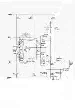
See the second and the third attachment for these protection circuits.
So in case of @kinesphere, the fact that after having disabled the soft start circuit the Amp trips, most likely means that the LS output exceeds it's allowed DC offset.
But to get the Offset pot in the right position, the DC offset sense function has to be temporarily disabled.
That can easily be done by shorting the 10K resistor on the right corner of the second attachment, see #133 for it's position on the RP-3 board.
After having adjusted the output offset voltage, the short on the 10K resistor has to be removed and hopefully the Amp is working now.
What still has to be done is adjust the Bias current to 2.5Amp which will give a 500watt load on the mains supply.
Last but nut least is finding out what's broken on the soft start circuit, but that's yet to come.
Hans
Is your first name Lim or is it KweeSong ?
Anyhow, to answer your questions.
The soft start circuit on the AP-5 board in #125 is not the same as on the AP-3 board.
But in both cases, two diodes couple to the output stage as shown in #106, thereby making a short between the two points that I called Y++ and Y-- during start up and at shut down.
Mark Levinson calls these points Pos_Drive and Neg_Drive as I found out later, but at the time I did my reverse engineering I had no documentation at all and had to select my own names.
By shorting those two point to ground, the output stage is no longer biased and current through all transistors in the output stage (fitted to the 4 big heatsinks) is zero.
The two diodes on the AP-5 are called CR106 and CR107 and on the AP-3 board D403 and D404.
See first Image below.
So when lifting these diodes, the soft start function is completely disabled.
Also notice that when the +55V and the -55V are not within 100mV in absolute value, that when the Mosfet Q103 closes and thereby shorts the bases of the two transistors together, the two 10K resistors will have their junction voltage at halfway the positive and negative voltage.
But since both emitters are still connected to ground, one of the transistors will start drawing current when the positive and the negative supply are not equal.
This leaking current will cause distortion.
Now the offset pot won't do anything when the soft start circuit doesn't release the short-circuit.
So now with the disabled soft start by lifting diodes, the output stage will start conducting current, but when the offset pot has been turned quite a bit, a large offset voltage may appear at the output.
Now the RP-3 comes into action, where several voltages are monitored, the +/-80V, the +/-55V and also the offset voltage at the LS output.
And finally three thermal switches have to be closed and no overload at the LS output has to be the case.
In all those cases when something is not correct, a Thyristor will be triggered that will cause the Main switch on the Amp's front side to trip.
See the second and the third attachment for these protection circuits.
So in case of @kinesphere, the fact that after having disabled the soft start circuit the Amp trips, most likely means that the LS output exceeds it's allowed DC offset.
But to get the Offset pot in the right position, the DC offset sense function has to be temporarily disabled.
That can easily be done by shorting the 10K resistor on the right corner of the second attachment, see #133 for it's position on the RP-3 board.
After having adjusted the output offset voltage, the short on the 10K resistor has to be removed and hopefully the Amp is working now.
What still has to be done is adjust the Bias current to 2.5Amp which will give a 500watt load on the mains supply.
Last but nut least is finding out what's broken on the soft start circuit, but that's yet to come.
Hans
Attachments
Dear Hans,
Thank you for the detailed explanation. I will study your explanation more closely but I did get the gist of it. 👍
Ok. For Chinese we wrote our name with the family name first. So in Singapore I will always write as such:
Lim Kwee Song
So my name is Song (that’s what my friends call me. Song is Chinese character is Pine tree. Kwee is my middle name. So my family name is Lim.
On an international front I will write my name as :
KweeSong Lim
So less confusion.
😊
Dear Song,
I may have overloaded you with info, if so, sorry for that.
But in case you are interested in even more details, just let me know.
Hans
I may have overloaded you with info, if so, sorry for that.
But in case you are interested in even more details, just let me know.
Hans
Information on working of amplifiers is never too much for me. 😊. Thank you very much for sharing your experience and expertise.
J
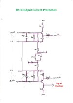
When you look at the first image below that was also in #136, you will notice that the upper part will just like the lower part force the transistor into conduction when overload is occurring, but this won’t lead in any way to tripping the amp.
Configured like this, the upper part could just as well have been discarded, a design flaw ?
That’s why I changed this circuit to let the amp trip not only on negative but also on positive overload.
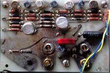
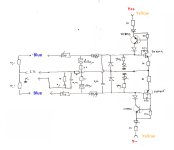
But ML also added a second current limit circuit on a separate Output Board that’s attached to the LS output sockets, see second and third attachment.
This Output Board circuit doesn't let the amp trip but should just limit the output current.
There are however a few issues to be mentioned that I disliked:
1) It's connection through yellow and blue wires via the Motherboard to the amplifier, could be regarded as radiating antennas.
2) but a more serious problem is that the two transistors pairs at top and bottom, are forming resp. PNPN and NPNP thyristors.
Once triggered by overload, they can only be reset by switching the amp off and on, but in the meantime they form a permanent current path between LS out and the driving voltages Y++ and Y-- thereby permanently reducing the Bias current in the output stage.
Point is that there is nothing to tell you that the "Thyristors" were forced into conduction but performance will be degraded.
For that reason I have simply pulled the yellow and blue wires from this output board and have the (modified) RP-3 board to switch off the amp when overload happens.
So the amp is still completely short circuit and overload protected, but in all those years this never happened because the combined output transistors SOA are far beyond normal use.
IMO, less is more.
Hans
So, here you go.Information on working of amplifiers is never too much for me.
When you look at the first image below that was also in #136, you will notice that the upper part will just like the lower part force the transistor into conduction when overload is occurring, but this won’t lead in any way to tripping the amp.
Configured like this, the upper part could just as well have been discarded, a design flaw ?
That’s why I changed this circuit to let the amp trip not only on negative but also on positive overload.
But ML also added a second current limit circuit on a separate Output Board that’s attached to the LS output sockets, see second and third attachment.
This Output Board circuit doesn't let the amp trip but should just limit the output current.
There are however a few issues to be mentioned that I disliked:
1) It's connection through yellow and blue wires via the Motherboard to the amplifier, could be regarded as radiating antennas.
2) but a more serious problem is that the two transistors pairs at top and bottom, are forming resp. PNPN and NPNP thyristors.
Once triggered by overload, they can only be reset by switching the amp off and on, but in the meantime they form a permanent current path between LS out and the driving voltages Y++ and Y-- thereby permanently reducing the Bias current in the output stage.
Point is that there is nothing to tell you that the "Thyristors" were forced into conduction but performance will be degraded.
For that reason I have simply pulled the yellow and blue wires from this output board and have the (modified) RP-3 board to switch off the amp when overload happens.
So the amp is still completely short circuit and overload protected, but in all those years this never happened because the combined output transistors SOA are far beyond normal use.
IMO, less is more.
Hans
Attachments

- Home
- Amplifiers
- Solid State
- Mark Levinson No. 20.6 Repair