I agree @Pars , I told my wife Hans is the angel of amplifiers who came to save me, haha. So patient and attentive, thank you so much Hans, we need more people like you in the world. Thanks for the recommendation as well Pars, I'm getting some of these washers.
Proceeding now with the final details, I removed the RP-3 wire, and the unit powers up as it should. Next step is to put back the diodes and test I believe? How safe is to power up this amp without a load? After putting back the diodes, I should have a dummy load connected, right?
Proceeding now with the final details, I removed the RP-3 wire, and the unit powers up as it should. Next step is to put back the diodes and test I believe? How safe is to power up this amp without a load? After putting back the diodes, I should have a dummy load connected, right?
The amp is completely safe with load.
Just try to find out how disturbing the plop at switch on and switch off is.
When acceptable, then leave things as they are now, else we will have to repair the soft start circuit that is definitely broken.
Hans
Just try to find out how disturbing the plop at switch on and switch off is.
When acceptable, then leave things as they are now, else we will have to repair the soft start circuit that is definitely broken.
Hans
Then leave things as they are now.
The soft start has no interaction at all when playing music.
Hans
The soft start has no interaction at all when playing music.
Hans
I could leave it like this I guess..but then the amps won't be fully repaired? You don't think it's worth trying to fix the soft start? And could by any chance the soft start work now the shorts have been removed and the DC offset has been adjusted?
Yes! All working well!!!! Thank you so much Hans and Song! Both amps are measuring similar levels:
At -6dBu input, output is 19.8dBu; THD+N is 0.030%; IMD: 0.007%
At 0dBu input, output is 25.8dBu; THD+N is 0.020%; IMD: 0.010%
Sounds beautiful. Only thing I noticed now is one amp's power red LED stopped working, and it was already intermittent as sometimes it would not work. I will investigate this further to see if I can fix it, it should be a simple thing I imagine. Apart from that, all good.
Lessons learned so far:
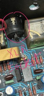
1) Soft start can be bypassed by cutting those diodes on AP-3.
2) DC-offset out-of-range/transistor safeguard, can be bypassed by shorting a resistor on RP-3.
3) Now we have voltage levels of multiple test points on AP-3 that can be useful for future reference.
4) The 9000uF caps need replacing after a while (both I had were leaky).
5) Mr Lim's showed the impossible can be achieved with his custom jigs and impressive inspection skills, plus so many observations on the ML such as the protection circuit that monitors the following:
a. excessive DC offset at the amp output
b. Over temperature.
c. Over current / short circuit
d. Unregulated power rail over voltage
e. Regulated power rail over voltage
And we now also know the SCR can be the culprit if the amp is tripping. I'm trying to summarise this long thread but there are many more details.
Thank you all, all this is very much appreciated.
At -6dBu input, output is 19.8dBu; THD+N is 0.030%; IMD: 0.007%
At 0dBu input, output is 25.8dBu; THD+N is 0.020%; IMD: 0.010%
Sounds beautiful. Only thing I noticed now is one amp's power red LED stopped working, and it was already intermittent as sometimes it would not work. I will investigate this further to see if I can fix it, it should be a simple thing I imagine. Apart from that, all good.
Lessons learned so far:
1) Soft start can be bypassed by cutting those diodes on AP-3.
2) DC-offset out-of-range/transistor safeguard, can be bypassed by shorting a resistor on RP-3.
3) Now we have voltage levels of multiple test points on AP-3 that can be useful for future reference.
4) The 9000uF caps need replacing after a while (both I had were leaky).
5) Mr Lim's showed the impossible can be achieved with his custom jigs and impressive inspection skills, plus so many observations on the ML such as the protection circuit that monitors the following:
a. excessive DC offset at the amp output
b. Over temperature.
c. Over current / short circuit
d. Unregulated power rail over voltage
e. Regulated power rail over voltage
And we now also know the SCR can be the culprit if the amp is tripping. I'm trying to summarise this long thread but there are many more details.
Thank you all, all this is very much appreciated.

Dear K,
Yes indeed we have people like Hans who is very kind and patience in sharing his experience.
That was the reason I documented my story. I had learned a lot from the internet and forums and YouTube how to video.
I wanted to share what I had learned and am very sure it will be helpful to somebody in future looking for information. My way of paying back to the community.
Your summary is indeed very useful too.
Dear Hans,
You are very knowledgeable and very patient. Kudos to you. The world needs more people like you.
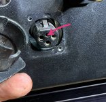
I remembered one time I asked a simple question on a different forum on how to remove an XLR socket from the back panel and I was very quickly brushed off by a few experienced persons. What they said “if you don’t even know how to remove the socket you have no business touching the inside of the amp!” 😞
The thing is that Krell XLR sockets connected to the back panel is very special. If one does not know, it is very difficult but if someone points out to you. It is very simple.
Normal XLR socket with pins soldered to the PCB could not be removed unless one desolder the pins and remove it.
In this particular case it could not be removed as it cannot be desoldered and impossible to remove the PCB without removing the xlr socket from the back panel.
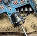
Fortunately, there are nice and kind people around too. I was directed to use a small screwdriver to release a latch inside the socket and the XLR separated into two sections. The Krell XLR has a fourth hole where the latch is located. Inserting a flat screwdriver and and making an anti clockwise turn releases the latch.
Thanks again to Hans for the patience and help. 👍👏🏻👏🏻❤️
You are very knowledgeable and very patient. Kudos to you. The world needs more people like you.
I remembered one time I asked a simple question on a different forum on how to remove an XLR socket from the back panel and I was very quickly brushed off by a few experienced persons. What they said “if you don’t even know how to remove the socket you have no business touching the inside of the amp!” 😞
The thing is that Krell XLR sockets connected to the back panel is very special. If one does not know, it is very difficult but if someone points out to you. It is very simple.
Normal XLR socket with pins soldered to the PCB could not be removed unless one desolder the pins and remove it.
In this particular case it could not be removed as it cannot be desoldered and impossible to remove the PCB without removing the xlr socket from the back panel.
Fortunately, there are nice and kind people around too. I was directed to use a small screwdriver to release a latch inside the socket and the XLR separated into two sections. The Krell XLR has a fourth hole where the latch is located. Inserting a flat screwdriver and and making an anti clockwise turn releases the latch.
Thanks again to Hans for the patience and help. 👍👏🏻👏🏻❤️
Attachments
I have one practice I usually do as a first pass check after visual inspection of the board for any virtual evidence of burnt components or leaking or bulging capacitors. It is to do a multimeter check on all transistors and diodes. Setting multimeter to diode test mode and measure all PN or NP junctions of transistors and diodes. This gives a gross check if any PN,NP junctions are punctured short or open. Measure PN or NP junction for forward diode voltage of 0.5-0.6V.
In K case this will be helpful as we don’t have an extension board and probing is impossible and having to resort to soldering fly leads to measure nodes voltages.
Not sure if it would have caught the shorter collector pins for the two transistors. Haha.
In K case this will be helpful as we don’t have an extension board and probing is impossible and having to resort to soldering fly leads to measure nodes voltages.
Not sure if it would have caught the shorter collector pins for the two transistors. Haha.
Hi Song,
Interesting to hear about the XLR, I have replaced many in the past but never came across one like this.. So that's good to know!
I normally do this diode test with the transistors too, but in my case, the washers were set in a way that I thought those were shorting in purpose... although I could have noticed this shouldn't be like that, just by looking at the tracks. Oh well, never trust an irregular set of screw washers. 😅
Thanks to Hans and Mr. Lim!!Dear Hans,
Thank you for sharing and pointing out the circuit. Even if I had traced it out it would have stumped me. I probably clild understood the mosfet shunting out the base current to the output transistors but the function of The left side of the circuit would have puzzled me 🤔
Thanks again. 👍. Good job.
Good to know there is a guru out there I can rely on if I have to troubleshoot another ML amp in future.
😊
Absolutely eye opening and lots to be learned!
- Home
- Amplifiers
- Solid State
- Mark Levinson No. 20.6 Repair