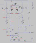

Point 5 can be found on the metal case of Q410, point 6 on the metal case of Q406 and point 7 can be found on Q400's collector.
Point 14 can be found on R471.
Point 4 is hard to reach and should be left for the moment.
You can also leave point 10 because it's Vbe voltage is only 0.3Volt.
What I would like to add to your measurements is to connect your multimeter in the current setting and measure between the collector of Q400 and the -55V supply voltage.
We have to solve the mystery where the 60mA current flowing through R422 is going to.
So in fact you should measure 60mA.
Success
Hans
Don't measure the current from Q400 to -55V.
Because there is only one way I can get what you just measured.
Point 7 at 1,7mV means that Q424's collector has a short to ground.
It could even be that R446, 604R has been blown into zero ohm.
So carefully check the PCB, Q424 and R446 what's wrong.
The other thing has more to do with supply voltages that are varying between measurements, so please redo de measurement on R423, R422 and R471, but now measured directly on both sides of the resistors.
Hans
Ok Hans, I did check and it was 0, no current through Q400 to -55V. I will check the possible short now, the resistors and take new measurements.
No current from Q400's collector to the -55V would be even more unexplainable.
When Q400 has an interrupted collector, where does the current flowing through R422 go to.
It can't vanish into thin air.
So I'm curious to see what you measure now on R423, R422 and R471.
Hans
When Q400 has an interrupted collector, where does the current flowing through R422 go to.
It can't vanish into thin air.
So I'm curious to see what you measure now on R423, R422 and R471.
Hans
The most likely cause seems now to be that Q400, the MJE15031 is dead.
But before making that final conclusion I must see the voltages on the three above mentioned resistors.
Hans
But before making that final conclusion I must see the voltages on the three above mentioned resistors.
Hans
R446 reads 600 ohms, so it's fine. R423 and R422 10 ohms, both good. R471 is a bit tricky to measure, will need to access the back.
But I realised something... when I was replacing caps of the first unit, I remember that when I put the transistor screws back (at the back of this board), the unit wouldn't power on (or tripping, not sure). Then I realised the screws had some washers to protect the transistors' collectors from shorting, and I copied the way it was from the other unit. Two are still shorting, maybe they shouldn't?? I can't see Q401 in your simulation. Its collector is shorting with Q400's collector. Same for Q404 and Q405. This is the same for the second AP-3 I have here.
But I realised something... when I was replacing caps of the first unit, I remember that when I put the transistor screws back (at the back of this board), the unit wouldn't power on (or tripping, not sure). Then I realised the screws had some washers to protect the transistors' collectors from shorting, and I copied the way it was from the other unit. Two are still shorting, maybe they shouldn't?? I can't see Q401 in your simulation. Its collector is shorting with Q400's collector. Same for Q404 and Q405. This is the same for the second AP-3 I have here.
Attachments

Last edited:
Possibly someone had tried to repair this before (these units went for repair in the past and were covered in dust as they were left in limbo for years) and lost some plastic washers. I just assumed the washers were put on a certain way, it seems some are plastic and others are conductive.. but now that I see the tracks, it doesn't make sense these transistors shorting, does it? 🤔
They are shorting Q400 and Q405 collectors to ground.
They are shorting Q400 and Q405 collectors to ground.
Last edited:
Wow, this is very important new information that changes everything we measured so far.
This is the reason that current seemingly disappeared.
All medium power transistors should be isolated from under their screwhead, if not they will be electrically connected to the heatsink and with each other, a recipe for disaster.
So now we have to start all over again after you have isolated all screw heads with washers below the six power transistors.
Points 1 to 14, except point 4.
Hans
Yes, I will try to get some good washers like that. For now I lifted the screws a bit and added some tape. Here are the new measurements:
1: 54.7V
2: 53.6V
3: 53.3V
4: not measured
5: 52.1V
6: 51.3V
7: 630mV
8: 18mV
9: -52.3V
10: -53V
11: -53.2V
12: -55.2V
13: 51.7V
14: 53.3V
1: 54.7V
2: 53.6V
3: 53.3V
4: not measured
5: 52.1V
6: 51.3V
7: 630mV
8: 18mV
9: -52.3V
10: -53V
11: -53.2V
12: -55.2V
13: 51.7V
14: 53.3V
You are the luckiest guy in the world.
I had expected several parts to be fried, but everything seems to work properly now.
Adjust the voltage at the output to zero volt and measure the voltages on both sides of C430.
Then measure the current drawn from mains.
Hans
I had expected several parts to be fried, but everything seems to work properly now.
Adjust the voltage at the output to zero volt and measure the voltages on both sides of C430.
Then measure the current drawn from mains.
Hans
haha I hope that's all!! Just one more thing, should I remove the wire on that resistor, which disabled the offset safeguard? Or put the diodes legs back in place? Because atm the outputs are measuring from 6.2V to 6.8V, and the pot doesn't seem to change less or more than this.
Yes indeed, remove the wire.
But your softstart circuit is really damaged so don’t connect the diodes.
Hans
But your softstart circuit is really damaged so don’t connect the diodes.
Hans
Good, it's 0.01V now. C430 is -2.3V and +2.4V. Current draw is 3.6A (530W). I will continue tomorrow, thanks Hans!
These normally work well for insulated shoulder washers. Pay attention to the fastener size and the length.
https://www.mouser.com/ProductDetail/Aavid/7721-7PPSG?qs=NqprlHOmxN1c1LnnOZYpOw==
https://www.mouser.com/ProductDetail/Aavid/7721-7PPSG?qs=NqprlHOmxN1c1LnnOZYpOw==
Even though I don't have a dog in this hunt and don't own any ML equipment, I've been following this thread. Hans, you are extremely patient in your help of people with issues with their Levinson equipment, give very clear directions on how to proceed, and are very knowledgeable. Kudos to you!
- Home
- Amplifiers
- Solid State
- Mark Levinson No. 20.6 Repair