Hi Hans,
Thanks for the explanation. I did as you suggested, shorted the 10K (R249 of RP-3) and powered up the amp without a load. Now it doesn't trip, so it skips the offset safeguard, but I couldn't get the offset to 0, it won't go lower than 140mV. Does the pot need to be changed while the unit is ON? It's a bit awkward to reach that little pot, so I've been turning it with board outside the amp, then putting it back and switching it on.
Thanks for the explanation. I did as you suggested, shorted the 10K (R249 of RP-3) and powered up the amp without a load. Now it doesn't trip, so it skips the offset safeguard, but I couldn't get the offset to 0, it won't go lower than 140mV. Does the pot need to be changed while the unit is ON? It's a bit awkward to reach that little pot, so I've been turning it with board outside the amp, then putting it back and switching it on.
I am sure back at the ML factory they definitely have an edge connector extender board to raise the board up to facilitate adjustment. For us it is really very inconvenient.
Yes, you are right.I am sure back at the ML factory they definitely have an edge connector extender board to raise the board up to facilitate adjustment. For us it is really very inconvenient.
The big problem is though to get the connectors from AVX/Kyocera that are currently only available from companies trading in NATO parts for ridiculous prices.
Much cheaper is to buy a few long nylon rods and to shape the end to fit the trimmer pot.
Hans

But does it need to be changed on the go? The pot does change values when I blindly do it externally. I can go up in numbers, but not lower than 140mV as it seems to have reached the max position of the pot.
Sorry that I have to ask, but are you sure that you have cut the right two diodes ?Hi Hans,
Thanks for the explanation. I did as you suggested, shorted the 10K (R249 of RP-3) and powered up the amp without a load. Now it doesn't trip, so it skips the offset safeguard, but I couldn't get the offset to 0, it won't go lower than 140mV. Does the pot need to be changed while the unit is ON? It's a bit awkward to reach that little pot, so I've been turning it with board outside the amp, then putting it back and switching it on.
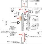
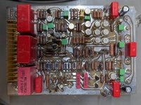
If so the next step will be to measure the current the amp is pulling from the mains, or alternatively and more direct, measure the voltage on either R22 or R23 on the Motherboard's backside, the 0.1R resistors that will tell you precisely what bias current is flowing, see first attachment.
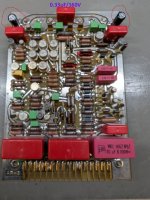
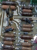
Then please go to 0.33uF/160V red cap , as indicated in the second image below and
1) carefully measure the voltages on both sides of this cap with reference to Gnd.
2) put your multimeter in the current mode and now put the probes on both sides of this cap.
You should measure ca. 40mA.
When this all seems acceptable, then there is definitely more wrong with the amp, but don't worry we will find the cause
Hans
Attachments
Hi Hans,
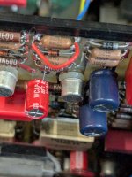
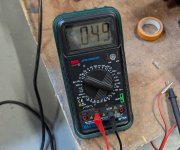
I wasn't sure about R22 and R23 as the components seem different on this motherboard (there is a pot there too), but I measured the amps from the wall and it seems it's taking 0.233A (image 1). Yes, the diode legs have been cut and the resistor is shorting to ground (see images attached).
The voltages from the capacitor points to ground are 532mV (+DRIVE side) and 360mV (-DRIVE), and the current between them seems super low, if I did it correctly, it reads .049mA.
Thanks.
Attachments
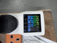
That was really fast. 240V*0.233A is 55.9Watt, so not even close to the 500Watt it should be.
As a matter of fact, I wasn't clear enough but R22 and R23 are on the backside of the amp, but don't bother at the moment.
And also the 49uA flowing when the 0,33uF cap is shorted is way too low, so there is more broken in your amp as just the slow start circuit.
The voltages on the cap should be resp. ca., +2.3V and -2.3V so what you measured is far off.
This means we have to go down much deeper into the amp.
I'll draw the circuit diagram in LTSpice with all relevant components, that makes it easier to tell you what to do.
Just a moment.
Hans
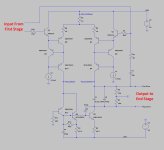
Here's the circuit diagram for the second stage, drawn and checked on it's proper working in LTSpice.
The component numbers do not match with ML numbers for as far they are visible on the PCB.
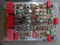
First thing to check is the current flowing in what's R9 in my diagram.
This should be around 90mA, resulting in 900mV over the 10R resistor.
This 10R resistor is indicated with a red circle in the attachement.
And also measure the voltage on the 10R resistor directly above this one, that should measure ca. 45mA.
Hans
P.S. Maybe you can also make a sharper picture of this AP-3 board.
The component numbers do not match with ML numbers for as far they are visible on the PCB.
First thing to check is the current flowing in what's R9 in my diagram.
This should be around 90mA, resulting in 900mV over the 10R resistor.
This 10R resistor is indicated with a red circle in the attachement.
And also measure the voltage on the 10R resistor directly above this one, that should measure ca. 45mA.
Hans
P.S. Maybe you can also make a sharper picture of this AP-3 board.
Attachments
Thanks a lot for this Hans. The 10R resistor indicated in the photo measures -0.94V across its two sides, 53.7V to GND, and the other end 54.7V to GND.
The other resistor, above this one, measures 0.933V across its two sides, and the ends to GND are 53V and 54V.
Sharper photo attached.
The other resistor, above this one, measures 0.933V across its two sides, and the ends to GND are 53V and 54V.
Sharper photo attached.
Attachments
Ok that’s bringing us one step further.
So only the left leg of the second stage is conducting.
Several possibilities
1) the first stage doesn’t provide equal voltages or
2) one of the transistors in the right halve has been fried.
So let’s first investigate the first possibility.
In the LTSpice circuit, the bases of Q1 and Q7 will have to be connected to give equal input voltages.
For achieving that, solder a wire from the two resistors as shown on the AP-3 board and measure again the two 10R resistors you just measured.
Hans
Attachments
hmm OK.. so now with the wire across, we have:
bottom resistor (R423): 0.94V across (same as before); 7.25V one side, 6.36V the other side.
top resistor (R422): 0.46V across, 53.7V one side, 5.86V the other side (which before was 54.7V).
bottom resistor (R423): 0.94V across (same as before); 7.25V one side, 6.36V the other side.
top resistor (R422): 0.46V across, 53.7V one side, 5.86V the other side (which before was 54.7V).
There is something wrong in your measurement.
R423 has still 0.94V, exactly as it should be, but 7.25V and 6.36V can't be true because one side is connected to the +55V supply.
R422 now has 0.46V, also fully correct. One side 53.7 seems o.k. but the other side must then be 53.7-0.46 = 53.3 and not 5.86V ???
Hans
R423 has still 0.94V, exactly as it should be, but 7.25V and 6.36V can't be true because one side is connected to the +55V supply.
R422 now has 0.46V, also fully correct. One side 53.7 seems o.k. but the other side must then be 53.7-0.46 = 53.3 and not 5.86V ???
Hans
Sorry Hans, you are right! I made a mistake, my ground was in the wrong place. The voltages read 53V and 53.9V.
and the top resistor 53.3V and 53.7V. I've been connecting the probe into the chassis ground, then at the moment I had mistankely connected into the negative output and didn't realise 🙄
The indication now is that the second stage is functioning properly, but before we go to the first stage I would ask yo to measure the current when putting your probes on the 0.33u 160V cap, like you did before.
This should now be ca. 45mA.
When true, measure again the current from the mains.
Hans
This should now be ca. 45mA.
When true, measure again the current from the mains.
Hans
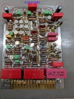
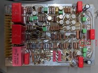
I come back from my previous conclusion and think that a MJE15030 power transistor is broken, see encircled area, the transistor sits on the backside.
When measuring the 0.33uF 160V cap, I expect you to find will find that both points are above 50Volt.
If so, this should confirm my suspicion.
This can also be tested by doing the diode test with your multimeter.
From base to emitter and from base to collector you should see a diode.
When the base to collector is interrupted you won't see this diode.
Hans
Attachments
Hi Hans! I'm back on it...so, the cap voltages, yes, around 50V. The current across is giving me 5mA, not 50mA.
The Q402 (sorry, I'm not sure of the number in your simulation, Q4?) transistor reads (from positive to negative):
B-C = 1. (OL), measuring the resistance is around 10K
B-E = 707
C-B = 550
C-E = 1.184
E-B = 566
E-C = 669
It seems you're right about the transistor then, it's faulty, right? I checked the other AP-3 from the second unit
(which is also faulty), and the measurements are exactly the same.
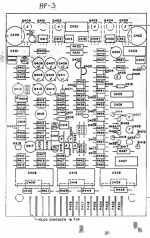
Ah. you have a placement diagram with component numbers, that makes life much easier.
I was talking about the MJE15030 which in my LTSpice was Q5 and in ML´s number Q403.
So can you measure the collector and emitter voltages of Q403 and Q405 with reference to the negative supply.
I expect both emitters to be ca. 2.2Volt above the negative supply.
Hans
I was talking about the MJE15030 which in my LTSpice was Q5 and in ML´s number Q403.
So can you measure the collector and emitter voltages of Q403 and Q405 with reference to the negative supply.
I expect both emitters to be ca. 2.2Volt above the negative supply.
Hans
- Home
- Amplifiers
- Solid State
- Mark Levinson No. 20.6 Repair