A job well done, my compliments.
One question: I read that you adjusted while testing the bias to 1 Amp.
When the job was finished did you further adjust the bias?
Because 1Amp means 16Watt@8R max in Class A instead of up to the 100Watt@8R max as intended by ML.
Hans
One question: I read that you adjusted while testing the bias to 1 Amp.
When the job was finished did you further adjust the bias?
Because 1Amp means 16Watt@8R max in Class A instead of up to the 100Watt@8R max as intended by ML.
Hans
It’s 1A bias over +/- 55V voltage rail. It’s not 16W class A. Haha.
This bias is constant regardless of the output voltage rail. On the bench I tested it at +/- 10V. When I raised the rail voltage this remains at 1A
This bias is constant regardless of the output voltage rail. On the bench I tested it at +/- 10V. When I raised the rail voltage this remains at 1A
I was talking about 16Watt in a 8R speaker as maximum in Class A when bias is only 1A, above 16Watt it will be Class B.
This has nothing to do with the +/-55Volt supply voltage.
In fact a properly adjusted 20.6 consumes 500Watt and this power remains almost constant up to 100Watt in 8R.
Hans
This has nothing to do with the +/-55Volt supply voltage.
In fact a properly adjusted 20.6 consumes 500Watt and this power remains almost constant up to 100Watt in 8R.
Hans
Sorry misunderstood you. You are right about your observation.
I checked my notes again. The bias current of 1A I quoted was what I adjusted and read from my bench power supply during testing with my test jig with one output transistor pair.
When the amp was fully assembled, you were right it was drawing about 400 plus watts from the mains. It was about the same idle power on the working channel and both channel heatsinks temp were the same.
So I did not adjust the bias current.
Thanks for pointing out. Good observation.
😊
Here you see the difference between 1A Bias and 2.5A Bias.
In Red you see the 40Vpeak output voltage to 8R, needed to get 100Watt.
Blue and Red are the currents through the 0.1R resistors that accumulate all currents from the positive and the negative output transistors.
And in Teal you see the summed current from the positive and the negative supply.
In case of 2.5A bias, the current through the individual output transistors drops to a few mA, but they still remain conducting.
The summed supply currents remains almost constant.
When going to 1A bias, the output transistors are no longer conducting all time and are operating in Class AB, with up to 16Watt in class A.
Hans
Bias 2.5A
Bias 1A
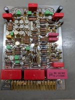
Are those 2 transformers just stuck in there with no kind of mounting hardware?A month ago I was contacted by Brandon at the DIYAUDIO forum. He had seen my post on Krell Amplifier repairs and asked if I am able to help repair his Mark Levinson No 20.6. One of the monoblocks was experiencing a fault and and kept tripping and shutting down the amplifier.
I said sure. Little did I know that I was embarking on the most challenging task in my last fifty plus years experience in tinkering with amplifiers.
It is going to be a long story and I will start updating this post moving forward. View attachment 1399465
Yes. I wasn’t able to loosen the mounting bolt. I believed it must have dislodged from the potted transformers. What I did was to keep them securely in place by putting a wedge between the gap. It is very stable and wouldn’t budge.
Dear Han, Wow, you are definitely more scientific than I am. I have not done any simulations before and would certainly like to learn and try sometimes soon. I hope.Here you see the difference between 1A Bias and 2.5A Bias.
In Red you see the 40Vpeak output voltage to 8R, needed to get 100Watt.
Blue and Red are the currents through the 0.1R resistors that accumulate all currents from the positive and the negative output transistors.
And in Teal you see the summed current from the positive and the negative supply.
In case of 2.5A bias, the current through the individual output transistors drops to a few mA, but they still remain conducting.
The summed supply currents remains almost constant.
When going to 1A bias, the output transistors are no longer conducting all time and are operating in Class AB, with up to 16Watt in class A.
Hans
View attachment 1420323
Bias 2.5A
View attachment 1420324
Bias 1A
Wry impressive. 👍👏🏻👏🏻👏🏻
U
I could never have constructed a board of my own without knowing every detail of the 20.6
Whenever I can help you in simulating, let me know.
Hans
Thx for your kind reply.Dear Han, Wow, you are definitely more scientific than I am. I have not done any simulations before and would certainly like to learn and try sometimes soon. I hope.
Wry impressive. 👍👏🏻👏🏻👏🏻
I could never have constructed a board of my own without knowing every detail of the 20.6
Whenever I can help you in simulating, let me know.
Hans

Amazing job Mr Lim and thank you so much for sharing this! I've been following the thread as I also received a Levinson amp for repair in December, which is not exactly the same, but a previous model, the original N.20. I believe it's all the same except for RP-5 and AP-5 being RP-3 and AP-3. My luck was that I received one working unit and one that was blowing up fuses, so I could compare parts. I replaced all the electrolytic caps except for the big ones until I found out one silver 9000uF screw cap was leaking as well. Replacing this made the unit work again. I also replaced all the caps for the working amp, which I was surprised was still working considering the state of the caps. Again, despite working, the same 9000uF showed signs of leakage at the bottom. I replaced these caps with 10 000uF 63V, I imagine this is acceptable. I did not replace the big blue caps, as you mentioned earlier, they should last for a very long time.
I also had some trouble with mechanical parts (one of the screw posts broke and it was impossible to fit the nut back in position, so I had to glue a new post with steel epoxy).
Yet, this repair is not complete as I still need to test them for distortion and frequency response. I'm still a beginner in the world of amp repairs, so if you could shed a light here that would be great.
I measured THD with a 100W 8ohm dummy load in parallel connected to a Neutrik A2 Audio System. For both amps I got similar results, at -50dBu input I had 30% THD, which decreased as I increased the input, but only until -30dBu where the distortion reached 5% and started to increase again (-25dBu = 9% THD). I realised then I should have checked the DC offset first! The reading was 1.4VDC for both amps. That seems pretty high.
Hans mentioned where the pots are earlier, but this looks different in the RP-3 and AP-3 and I'm not sure where to start and what order to follow. In my units I have 1 pot in the motherboard, 1 pot in the AP-3 and 2 pots in the RP-3. See images attached.
I tested the pot on AP-3, and it seems that it needs a few turns counter-clock-wise to reduce the DC offset, and from 1.4V it went to 1.25V, but I'm unsure if this is the right procedure. Some guidance here would be very much appreciated! Thanks!
Attachments
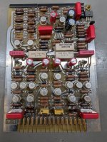
These two pots adjust the voltage regulator voltages.
My knowledge on distortion measurement is very limited. I believe Hans would definitely be a better person to advise. However those distortion figures are way too high if measurements were done correctly. You should be able to tell the music sure wouldn’t sound nice.
check the power drawn from the working vs the repaired amps. Both should be drawing in the hundreds of watts range if there is enough class A current bias.
Are you able to measure rail voltages ?
Your AP3 has only a single PCB board so that means only one adjustment pot. That should be the only one to adjust for DC offset.
With DC offset of more than one volt may point to some other problem.
Attachments
Thanks for your super fast reply Mr Lim! I think both amps have the same behaviour, so the 'working amp' is not a good reference. The power drawn at idle is 46W (240V/0.3A) and with a -3dBu 1000KHz input it's 95W, when I increase the signal to -2dB it trips. I will check the power rails and post back soon.
Thank you.
Thank you.
All versions of the ML20.X should draw 500Watt at idle.The power drawn at idle is 46W (240V/0.3A)
So, your measured 46Watt means that the end stage is not biased because it is shut off.
This of course causes a very high distortion.
The most likely cause is that the +/- supply voltages are not within 100mV, causing a soft start circuit to disable the output stage.
And yes, these two voltages are set with the two pots on the RP-3 board.
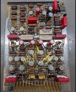
On the two corners at the top of your AP-3 board you have two large black electrolytics, encircled in the attachment.
Tell me what voltages you can measure here.
Hans
Attachments

Yes, as mentioned they should be within 100mV.The rail voltages are 54.8V and -55.3V. Is this too far off?
So you you have to adjust by trial and error by taking out the RP-3 board and turn one if the two pots, say the left one, by half a turn.
Put the board back in and measure again.
Continue doing this until the two supplies are within 100mV.
Hans
P.s. are you measuring on the two black caps ?
Hi Hans, thanks for your help! Before I had measured from the bottom (motherboard), now I checked again from the black caps and similarly I have 54.4V and -55.2. I will keep going down with the pot then to see if I can reach 100mV on the DC offset, currently at 1.25V.
- Home
- Amplifiers
- Solid State
- Mark Levinson No. 20.6 Repair