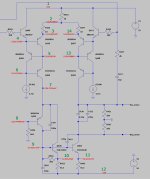
For as far possible, I have renamed all components in my LTSpice diagram to have the same numbers that ML uses.
That may prevent misunderstandings.
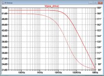
To be sure everything is correct, I have simulated the FR of this second stage, which seems O.K.
Hans
That may prevent misunderstandings.
To be sure everything is correct, I have simulated the FR of this second stage, which seems O.K.
Hans
Attachments


Wow, great, thanks for doing this. I measured these points to the negative rail:
Q403
Collector v: -101V
Emmiter v: 0V?
Q404
Collector v: -55V
Q405
Collector v: -55V
Emmiter v: 0V?
Q403
Collector v: -101V
Emmiter v: 0V?
Q404
Collector v: -55V
Q405
Collector v: -55V
Emmiter v: 0V?
Have you seen the order of BCE in #157 next to Q403?
What you measure is unfortunately of no use.
You should measure with one pin on the -55V and with the other pin on resp. the collectors and emitters from Q403 and Q405.
Q404 has nothing to do with this.
Hans
What you measure is unfortunately of no use.
You should measure with one pin on the -55V and with the other pin on resp. the collectors and emitters from Q403 and Q405.
Q404 has nothing to do with this.
Hans
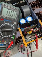
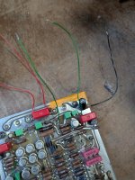
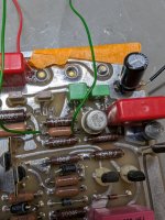
Yes, I followed the order and also double-checked the datasheet of each transistor. I measured Q404 as well just because it was 'easy to do it', as the collectors are connected to the back screws. For the emitters, I had to put wires. See image. The black wire is the negative voltage, if I connect the other probe to GND I can see that it's working. The green wire (emitter) to the black wire (negative voltage) is 0V. Please see the images to confirm it's correct.
Attachments
Yes this is absolutely correct.
That you measure zero volt on Q403's emitter, just means that no current is flowing, so the emitter hangs in the air, a clear sign that this transistor is fried.
But to be 100% sure I still would like to see Q405's emitter voltage and now also Q403's base voltage.
Hans
That you measure zero volt on Q403's emitter, just means that no current is flowing, so the emitter hangs in the air, a clear sign that this transistor is fried.
But to be 100% sure I still would like to see Q405's emitter voltage and now also Q403's base voltage.
Hans
Q403 base to negative voltage is 0V, Q405 emitter to negative 0V, however, if you what you mean is to check them with ground, then they both are -55V.
What you measure is a big mystery.
when you look at the LTSpice diagram that I made, R422 was measured as carrying 0.49V, or conducting 49mA.
This current will have to pass through Q410 and Q400.
From there it should go to Q405 and through R452, but seemingly it does not because Q405's base and emitter are both at zero volt.
So where is the current going to ?
When it does not go to Q405, the only other possibility is that Q424 is broken and that all current goes into R446.
If so, R446 should be measured, and when not having something like 50mV but ca. 30Volt, then this transistor is the one that's broken.
So please measure R 446, a 604R resistor, it's the second resistor below Q403
Hans
R446 shorts to the base of Q404, and to the collector of Q405... I have some schematics, but I'm unsure if I have it for AP-3 as some components don't seem to match, so it might be AP-4. I will take another look to see if any of this makes sense.
AP-4 is completely different from AP-3
Just follow my LTSpice diagram and you will see what I mean.
The base resistance from Q424 to Gnd, a 604R resistor and this one can hardly measure -55V.
So please measure R446, the second resistor below Q403.
One side should be Gnd and the other side is ??
Hans
Just follow my LTSpice diagram and you will see what I mean.
The base resistance from Q424 to Gnd, a 604R resistor and this one can hardly measure -55V.
So please measure R446, the second resistor below Q403.
One side should be Gnd and the other side is ??
Hans
The error is is still a mystery because measurements are not conclusive.
Therefore I would ask you to do a more thorough set of measurements.
In the attachment are 14 points marked, together with the voltages they should have for a proper working amp.
I would like you to enter the measured voltages in the excel sheet.
Hans
Therefore I would ask you to do a more thorough set of measurements.
In the attachment are 14 points marked, together with the voltages they should have for a proper working amp.
I would like you to enter the measured voltages in the excel sheet.
Hans
Attachments
Hi Hans, I only got back at the workshop. I believe Q405 collector was stated above to be -55V. I will take measurements of all the points you marked as soon as I can. Thanks
Hi Hans,
So far we have:
1: 54.7V
2: 53.8V
3: 53.2V
8: 0V
9: -55.1V
11: -55.4V
12: -55.4V
13: 51.6V
I'm unsure about points 10 and 14. Are you sure R456 is not R452 in your schematics? And R47, should it be R425 maybe? I will try to do the rest tomorrow, I need to access the back of the PCB for the missing points and wire from there.
Thanks, have a good evening!
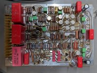
I will check the resistors you refer to, now that I have a sharper picture from your board.
Don't go to the back until absolutely necessary.
In the meantime I will analyze the data you already provided.
Hans
Don't go to the back until absolutely necessary.
In the meantime I will analyze the data you already provided.
Hans
- Home
- Amplifiers
- Solid State
- Mark Levinson No. 20.6 Repair