Hmm...my window is blackman harris 7, no smoothing. I didnt know the stepped sine fact so tried that too, but it truly does have that response (bottom is stepped sine). I do have 5.20.13, installed a few days ago when problems started.@Dendrobium
It is almost certain that problem is your measurement setup and REW settings.
FR response you get is exactly (within fraction of dB) what looks REW output of a perfectly flat amplifier or it’s loopback, if 1/48 smoothing + Flat-Top window are used. Smoothing reduces measured level with frequency increase.
However, automatic distortion and FR measurement using stepped sine option, ignores smoothing options from the standard FFT measurement setup in my REW version, so question remains how is that happening in your case.
Do you have latest REW version 5.20.13?
P.S.
Listening test should immediately make clear does that -15 dB at high frequencies really exist.
I was about to do your suggestion above (good idea btw), to check levels at gates of relevant components, but i thought ok lets plug it in first since we did verify it works fine, and has no dc offset, i have nothing to lose (doh, where was this thought days ago).
OK now get this...
I plug it in and it sounds perfectly fine (more than fine), and flat.
Just to dispell any doubts did a sweep with a measurement mic
All this pulling out hairs, replacing everything, turning amp into different amp and back...funny thing is im still driving it now with MOTU output (just for test, otherwise not enough drive level as expected), the same setup that was incriminating just minutes ago.
I have to apologise to you tombo and ZM....all this time you're been helping me patiently but all i had to do is plug it in...really, thanks a lot for your help and time...i guess no idea in the end what it was, since i can still do flat measurements of everything else with the same settings. Happy the Ali LD's are legit. Happy with amp (time to finally listen and enjoy).

All this pulling out hairs, replacing everything, turning amp into different amp and back...
 I’m sure your hair is in the same disarray after all this.
After a few days of having it i have to say amp is excellent, very effortless, detailed, punch is there too.
In my experience one of "best" i had so far...though i have not had privilege to sit down with SIT for few days like this
Best part is you dont even sacrifice any "objective metrics" either, hard to find an argument against it...who builds will not be dissapointed
Another ZM ampicus extraordinaire
Thanks again ZM and tombo

LuDEF remained in the shadow of its older brother SissySIT. Really undeserved, IMO.hard to find an argument against it...who builds will not be dissapointed
Now you can play with various front ends. 😀
frankly, LuDEF was sorta surprise ......... but most wakoo of them all is still - Old Soul
Yup exactly, really enjoying Aikido toob pre for now, thinking what to put in front next 🙂LuDEF remained in the shadow of its older brother SissySIT. Really undeserved, IMO.
Now you can play with various front ends. 😀
Heck, down the road could even build ZM's original front end, just put it in different box and same thing
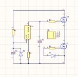
I have some time since I experiment with aluminium pcbs. The last attempt was with some shunt regs that run pretty nice.
Recently I took my chance to draw the Lu1014 and the cascode mosfet on the same alu pcb using the SO227(the hockey puck as we call it here) footprint and only smd components.
This will have to run at 20-25V and 1.5-2A so practically having ~45W max dissipating on the cascode mosfet which is a d2pak.
I found online some info saying that d2pak can do 50W if properly cooled. Not being sure of this I came to ask here for a suggestion(smd packages) for something else I can use if d2pak is not ok. Maybe use 2x dpak(dpak is smaller than d2pack) in parallel? or some other power package like HSOF-8 ? I have some IPT015N10N5ATMA1 in house that I can use.
Attachments
put everything, LU and surrounding circuitry, on Al pcb, and pads for IRFP240
just one hole more, no worries
just one hole more, no worries
you mean keeping the d2pak (to263 pack)?
there is a mistake with the pins, I will use only the 1st, 3rd and 5th so there will be 5mm spacing between the pins.
there is a mistake with the pins, I will use only the 1st, 3rd and 5th so there will be 5mm spacing between the pins.
no, what I meant is - put cascode IRFP240 outboard, so part having biggest dissipation is being directly on its own on heatsink
why bother with subpar component and think about longevity, when you can do it properly
I was thinking of making same arrangement, but in the end abandoned that idea - that should go as option with some existing amp ( say making LuDEF on Babelfish M25 basis), but that's just more complications in future (counseling phase)........besides, don't like cap being on same temperature as output device, and there are 2 electrolyts involved
It would have been easier like this, you simplify a lot the main pcb but as you say the caps cook faster at 60c than at 40c.
I'm just wondering if anyone found an advantage from doubling up the 50uF motor run caps on their PSU board outputs?........
I've got a single power supply board and 4-off 50uF Ducati caps. Is it worth trying all of them, or just use a pair? Thanks everyone
as always - more, the merrier
will you hear the difference , who knows
will you sleep better, only you can know
will you hear the difference , who knows
will you sleep better, only you can know
Hi all, Finally after almost a year I'm at the stage where I'll be powering up my LuDEF and putting it in a case...
I've a question about bolting the IRFP transistors directly to the PCBs.
Is there some reason (thermal, or otherwise) why they should bolt direct with no washer between the device and the board?
This will give a standoff height of approx 5.25mm with a mica/ Keratherm pad. I have a bag of 6mm standoffs and M3*12*0.9 washers. 5mm doesn't seem like a lot
5.25 is plenty of clearance, if you take care of not having any pin or wire on bottom side of pcb longer than that 
of course that you can put something in between mosfet and pcb, taking care to have enough contact area but also not to make short with bottom side tracks, in case of using metal piece (big washer)
piece of pcb ( bare) would be ideal, size of mosfet case
though, pcb being held in place at two mosfets; there is enough length leeway to front mounting hole, so you can freely use 6mm standoff ; 0.75mm difference in clearance is nothing to write home about
Hello again, I'm afraid I have another possibly silly question..
I've just replaced the output devices on a Teabag M2 with a matched quad of the Fairchild FQA devices - the amp is transformed!
I can see on the LuDEF that the IRFP240 could be replaced with the FQA16N25C, but what about the IRFP9140? Would changing either/ both of these Mosfets result in a lower noise floor?
Is there a Fairchild equivalent to the '91' device? (Could this also be used on the SissySIT 42?)
Would the FQA16N25C perform the same
task?
Do these devices need to be matched for this application?
Huge thanks
Last edited:
- Home
- Amplifiers
- Pass Labs
- LuDEF