yeah, but whatever Drek you choose as replacement for IRFP240, it is cascode - no change in sound
now, considering how dominant cascoded Lu cell is in output, I have doubts that any change in place of IRFP9140 will be of any significance
though, easy to try, leave what's best for you
M2 ...... I adore little jewel, and didn't/wouldn't/couldn't change one thing of it
for change, I made completely new amp (well, different enough) .......... or two
Whatever Fairchild N and P channel parts you used for the M2 should be fine here as well.
FQA12P20 & FQA16N25C
The FQA12P30 is a direct equivalent to the IRFP240.
LuDEF uses the IRFP9140 (not the 9240) is the FQA16N25 really suitable? Is there an FQA 9140 equivalent item?
The Fairchild's just seem to be lower noise
Last edited:

Why not? I seen some interesting stuff under 1v. When the things started to get more interesting the pot that controls the voltage on the gate of the cascode got to the lower limit of 0.9v and the fun finished there for now.
I think I want to try to go a bit lower than 0.9v like 0.5-0.6v. Is this possible?
I think I want to try to go a bit lower than 0.9v like 0.5-0.6v. Is this possible?
try and inform ...........
though, I'm not expecting things being so repeatable at 1V and sub, as they are at 2V4
though, I'm not expecting things being so repeatable at 1V and sub, as they are at 2V4
So all good if I go to 0.4-.5Vds?
the older graphs(scale in W) have the Vds at 2.5V and the never ones have it at 0.76V.
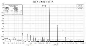
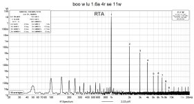
The measurements are for 25V rails and 1.6a bias, amp used as single ended this time.
the older graphs(scale in W) have the Vds at 2.5V and the never ones have it at 0.76V.
The measurements are for 25V rails and 1.6a bias, amp used as single ended this time.
Attachments

task:
-confirm both Uds variation with same graphs (ordinate in same units; maybe it is the same, but my old brain easily confused/suspicious)
-confirm uniformity between two channels; as I said, it's logical (me, I, my brain) to expect lesser behavior uniformity when going borderline
-confirm both Uds variation with same graphs (ordinate in same units; maybe it is the same, but my old brain easily confused/suspicious)
-confirm uniformity between two channels; as I said, it's logical (me, I, my brain) to expect lesser behavior uniformity when going borderline
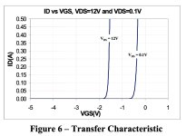
The data-sheet seems to say that you are free to experiment.... Nothing borderline about 0.4-0.5Vds as long as it does not vary to much with the signal.
However, as mighty mod points out, please present us the results in a consistent way so we don't have to guess too much. Personally I prefer dBV for Y-axis, but I do understand that that does require some minimal sound card calibration.
However, as mighty mod points out, please present us the results in a consistent way so we don't have to guess too much. Personally I prefer dBV for Y-axis, but I do understand that that does require some minimal sound card calibration.
Attachments
I was looking at the thd ratios and not at the db difference. I seen recently that usually the thd it`s quoted in db so yesterday I changed back from W to dbfs keeping an eye at the ratios which were the same.
Today measurements and the earlier ones were done into a 4ohm load.
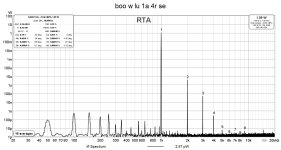
The first attachment is the right channel measured in the past with ~2.65vds for the lu.
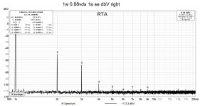
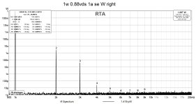
The second is the right channel measured now with ~0.88Vds for the lu.
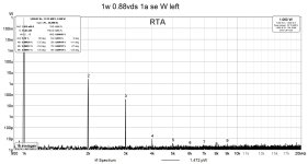
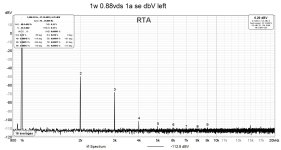
The third is the left channel measured now with same 0.88Vds for the lu. The improvement seems repeatable also on the second channel(the lus were matched for vgs and gm).
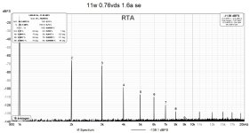
The fourth and fifth are measurements from today in dbV.
Later today(if possible) I will try to remove the pcbs from the amps and modify some component values to be able to get to a lower Vds and see what I get. It was interesting until now.
Today measurements and the earlier ones were done into a 4ohm load.
The first attachment is the right channel measured in the past with ~2.65vds for the lu.
The second is the right channel measured now with ~0.88Vds for the lu.
The third is the left channel measured now with same 0.88Vds for the lu. The improvement seems repeatable also on the second channel(the lus were matched for vgs and gm).
The fourth and fifth are measurements from today in dbV.
Later today(if possible) I will try to remove the pcbs from the amps and modify some component values to be able to get to a lower Vds and see what I get. It was interesting until now.
Attachments
I'd love to see those graphs with the IRFP240 swapped out for an FQA16N25C. I'm imagining that the low level background 'fuzz' will just disappear
Ups there is a mistake in my post above, I added the files in the correct order but when uploaded tothe site the order went crazy.
So in above post the order is like this
the 1st and 5th attachments are the measurements done today in dbV scale.
the 2nd and 3rd attachments are the measurements done today in W scale to be able to compare them with the past measurements with same scale.
the 4th attachment the measurement done in the past.
Sorry for the confusion.
@Dan K do you mean the mosfet that is used to cascode the lu? With low level fuzz do you mean the noise or the thd above 3khz?
Exactly what improvement do you see? To me THD is virtually identical between the 5 measurements (0.15% / 0.16% / 0.16% / 0.19% / 0.15%).The improvement seems repeatable also on the second channel
Your different scalings does not affect how REW calculates THD as this is a ratio.
Today I shown that the thd went from 0.19% to 0.15% at 1w and 1amp bias by lowering lu vds
Earlier I shown same thing but at 11w it went from 0.35% to 0.21% with 1.6a bias.
At 1w there is not much of a difference but at 11w there is a bit. At least we can call it lower thd if not improvement?
Earlier I shown same thing but at 11w it went from 0.35% to 0.21% with 1.6a bias.
At 1w there is not much of a difference but at 11w there is a bit. At least we can call it lower thd if not improvement?
Sure you can call it lower THD and an improvement 🙂
I just can't help not to compare with the values shown by ZM in the beginning of the thread, which seem an order of magnitude better.
I just can't help not to compare with the values shown by ZM in the beginning of the thread, which seem an order of magnitude better.
Yes, the cascode Mosfet. The noise / both@Dan K do you mean the mosfet that is used to cascode the lu? With low level fuzz do you mean the noise or the thd above 3khz?
FQA = F5*k1#g - Quiet - As! (also very expensive at £10 or so an item when they were in production, vs £2.5 for the IRFP)
Last edited:
- Home
- Amplifiers
- Pass Labs
- LuDEF