It´s exactly the same, with the advantage of *you* selecting exact voltage but more important, dissipating as much power as you wish.Ok.
That's not what I meant though.
I was thinking simpler like this.
You can use as many/large power transistors as you wish, with all the heatsink capability in the World as necessary.
Try that with simple zenering/clamping devices.
in parallel with a tweeter? I'd assume there would be a lot more capacitance that way.
And even easier? A fuse?
And even easier? A fuse?
Last edited:
 OT posts removed.
I post here the reason of my questions. I like the timbre of EL34 and I would like to find where it can be safely pushed, being aware that pushing a tube means shortening his life (a rule that applies to everything).
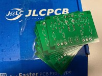
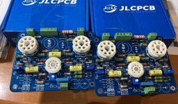
So the attached is the amp I'm starting to build (planned to run it on winter holydays), and here below the photos of the boards partially populated.


I have three feedbacks:
- a local feedback in voltage on EL34: 23% UL
- a local feedback in current on EL34 (Shade-like)
- a global feedback that injects only the distortion on the phase splitter
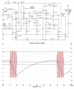
I'm waiting the power transformer (I already have the two 4k Raa output transformers), so no real results yet, but on simulations I have:
70 Wrms at 1% THD (with 2 Vrms on input)
DF 43 (yes, fortythree thanks to that kind of feedback)
PS
the filters around the global feedbcak circuit need to be adapted to the output transformers and will be determined when the amp will be running (at the beginning without gnfb, then with).
So the attached is the amp I'm starting to build (planned to run it on winter holydays), and here below the photos of the boards partially populated.
I have three feedbacks:
- a local feedback in voltage on EL34: 23% UL
- a local feedback in current on EL34 (Shade-like)
- a global feedback that injects only the distortion on the phase splitter
I'm waiting the power transformer (I already have the two 4k Raa output transformers), so no real results yet, but on simulations I have:
70 Wrms at 1% THD (with 2 Vrms on input)
DF 43 (yes, fortythree thanks to that kind of feedback)
PS
the filters around the global feedbcak circuit need to be adapted to the output transformers and will be determined when the amp will be running (at the beginning without gnfb, then with).
Attachments
Last edited:
zintolo,
What is the sound of a 70 Watt EL34 push pull amplifier that has 3 negative feedback loops, and so much distortion correction and such a high damping factor?
Does the "timbre" of an EL34 'come through' in such an amplifier?
I would like to know if anybody could hear the difference between EL34s versus KT77s in that amplifier.
Almost exactly the same tube data specifications, but the EL34 is a true pentode with a real suppressor grid (wires), and the KT77 Beam Power tube with Beam formers (instead of suppressor grid wires).
How about a double blindfold test?
Last edited:
I know how the two local feedback sound together. And I like it.
They permit to have triode like curves with more gain.
I will try soon how the third will sound and report here.
I would not expect it sounds bad a priori. Would you?
They permit to have triode like curves with more gain.
I will try soon how the third will sound and report here.
I would not expect it sounds bad a priori. Would you?
zintolo,
Is it possible . . .
How that amplifier will sound is perhaps mostly due to the following:
Lots of negative feedback . . . Resulting in low distortion and high damping factor.
And that the 'sound' depends less on "the sound of EL34 tubes".
Global negative feedback should improve the frequency response, should reduce the distortion, and should increase the damping factor.
One other thing that global negative feedback will give you is that at whatever low frequency x the low frequency power level finally saturates the output transformer laminations, the global negative feedback will make the saturation worse.
Last edited:
In most cases the sound will be most dependent on the sound reproduction system, the loudspeaker(s) in their baffles, the listening space & so on. The most difficult part of any audio system. And whether the listener has a hangover or a disagreement with 'the significant other'.🙂
My opinion!😀
My opinion!😀

6A3sUMMER,
I have to say that I’m curious to try this “distortion only” global negative feedback on a feedback configuration I already know and like. Damping can be reduced without affecting the gain of the amp at low wattages, and this is another thing I like of this global feedback.
I have margin on output trafos, at least between what Toroidy declares and what I get out from them. I hope it will help gnfb chasing low distortion.
But I agree with you that it could just be my own hype on that, and this could false my perception of its implementation.
jhsteward9, very true, I will perform the test in the usual room with my well known Klipsch trying not to get drunk nor to argue the day before. 🙂
Just one point: at low power levels, this gnfb has few-to-no feedback, whilst the gnfb increases when the power (so thd) increases.How that amplifier will sound is perhaps mostly due to the following: Lots of negative feedback . . . Resulting in low distortion and high damping factor.
zintolo,
I am not sure what you mean by your Post # 70.
Just for illustration, and simply an approximation, let me say this . . .
Take a push pull amplifier that does not have negative feedback of any kind, that puts out 1 watt with 316mV signal input.
If the amplifier is powerful enough, it will put out 10 watt with 1V signal input.
Suppose it has 1% harmonic distortion at 1 watt, and 3.16% harmonic distortion at 10 watt.
The error at 1 watt is 1%; the error at 10 watt is 3.16%
Take that same amplifier, but add just enough global negative feedback so the voltage gain is reduced by 3.16 (10 dB of negative feedback).
The amplifier will now put out 1 Watt with 1V signal input; and if the amplifier is powerful enough, it will put out 10 watt with 3.16V signal input.
Now, in a reasonably well behaved amplifier circuit . . .
Because of the added global negative feedback, it will have 0.316% harmonic distortion at 1 watt; and 1% harmonic distortion at 10 watt.
The global negative feedback reduced the distortion by 1/(3.16) at 1 watt; and the global negative feedback reduced the distortion by 1/(3.16) at 10 watts.
The harmonic distortion was reduced by 1/(3.16), but the ratio of power-versus-distortion remained the same:
With no feedback: 3.16 times more distortion at 10 watt versus at 1 watt.
With global negative feedback applied: 3.16 times more distortion at 10 watt versus at 1 watt.
The point is, the feedback Ratio with global negative feedback did not change, no matter whether the amplifier is putting out 1 watt, 10 watts (or 2 watts, or 5 watts).
The Ratio of gain reduction caused by the global negative feedback circuit is 1/(3.16) at all power levels (versus the higher gain of the same amplifier that does not have global negative feedback).
And the Ratio of harmonic distortion reduction caused by the global negative feedback circuit is 1/(3.16) at all power levels, versus the amplifier that does not have global negative feedback.
Low power output does not mean lower % of global feedback, the feedback ratio is fixed by the feedback resistive divider.
High power output does not mean higher % of global feedback, the feedback ratio is fixed by the same feedback resistive divider.
I hope that makes sense.
Last edited:
zintolo,
I am not sure what you mean by your Post # 70.
The point is, the feedback Ratio with global negative feedback did not change, no matter whether the amplifier is putting out 1 watt, 10 watts (or 2 watts, or 5 watts).
The Ratio of gain reduction caused by the global negative feedback circuit is 1/(3.16) at all power levels (versus the higher gain of the same amplifier that does not have global negative feedback).
Usually it is like that, yes, but not in this case.
Here the feedback that is injected on the other side of the phase splitter is NOT the full output signal scaled down as in all well known nfb circuits.
Here the signal from the output is scaled down and rephased, then compared (through a gain stage with one inverting and one non-inverting inputs, like an opamp or grid and cathode of a tube) to the signal at the input of the amp.
At the output of this gain stage, there’s only the difference between the input and the scaled down and rephased output, so there’s only the output distortion.
The other side of the phase splitter receives only the distortion as signal to correct the behaviour of the amp, and not the full signal.
This way when you are at low volume the gnfb is very low because the amp has very low distortion, and the amp works with very low gnfb.
When the power goes up, distortion goes up and the gnfb goes up as well.
In that circuit I have a triode phase splitter as the only gain stage before EL34.
There would be no reserve of gain to have a DF of 43 considering a loadline of 4k.
NFB is a ratio, how much is gain reduced compared to open loop, and as all ratios has no units.
Even if measured in dB, that still means a ratio, dB is just a convenient name, not a "unit".
The amp in your example will have lower feedback voltage at low levels , higher at high levels,but that does not mean ratio changes.
Even if measured in dB, that still means a ratio, dB is just a convenient name, not a "unit".
The amp in your example will have lower feedback voltage at low levels , higher at high levels,but that does not mean ratio changes.
Hi jmfahey,
with this kind of feedback, if the amp without feedback has no distortion, there's no gain reduction and the feedback signal is zero.
The feedback increases with the amount of distortion of the open loop amp (multiplied by the gain of the gnfb stage), not proportionally with the input or output signal per se.
I hope to have better explained it.
zintolo,
Do you have a readable schematic that will help us understand the principles that you are trying to communicate?
If so, would you please post the schematic on this thread.
I think we do not need the voltages, and do not need the currents.
We just need to see the signal paths, feedback paths, kinds of bias, and circuits such as phase splitter circuit, etc.
Or, is the circuit you are talking about proprietary?
Some Variable FB
Here are a few but none are considered audio HIFI!
Receiver AGC (Automatic Gain Control).
Expander/Compressor.
Tremelo in a Guitar amp if it has a NFB circuit.
Others may think of more.🙂😱
Here are a few but none are considered audio HIFI!
Receiver AGC (Automatic Gain Control).
Expander/Compressor.
Tremelo in a Guitar amp if it has a NFB circuit.
Others may think of more.🙂😱
Usually it is like that, yes, but not in this case.
At the output of this gain stage, there’s only the difference between the input and the scaled down and rephased output, so there’s only the output distortion.
The other side of the phase splitter receives only the distortion as signal to correct the behaviour of the amp, and not the full signal.
I know this must look right to you on paper, but it's simply not possible.
All good fortune,
Chris
Do you have a readable schematic that will help us understand the principles that you are trying to communicate? If so, would you please post the schematic on this thread.
The schematic was included in post #64 albeit in LTSpice format. It is your basic fully differential push pull amp not unlike some that I have built. It just has an extra opamp that compares the tube amp's scaled output to it's input generating an error signal. This signal is then applied to the non-input side of the tube amp's input diff amp.
At this moment my brain can't decide if this will work, create more distortion, or just turn into a big power oscillator.
Years ago when I used to repair EL34 guitar amplifiers I found short bursts at full power were the best for the maximum power test as many amps could kill G2. A one second burst should be suffice to capture data.
Like this? Done with an analogue gate I built about 20 yrs ago.🙂
The blue trace is the PS sagging under load.😱
Attachments
From #64
a global feedback that injects only the distortion on the phase splitter
To do that would need to reject the fundamental, by Wien Bridge maybe??
But at all frequencies?? Sounds like SSB (Single Sideband) Modulator.
Stuff the result back into the phase splitter? Weird!😱
Treat with Aspirin. Carefully!
- Home
- Amplifiers
- Tubes / Valves
- Lowest safe loadline: what is the limit?