The 'miracle' amplifier probably would give a troubled oscillating Williamson amplifier a run for its money . . .
The 'miracle' amplifier might go into power oscillation, depending on the exact circuitry and the output transformer.
If it works properly with one speaker, then try it on some other speakers, and watch the results!
Thanks for the note about Post # 64 and the LT Spice model.
But Software and I are not compatible.
Just my opinions.
Last edited:
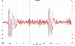
Like this? Done with an analogue gate I built about 20 yrs ago.🙂
The blue trace is the PS sagging under load.😱
Yes, as you started doing 20 years ago 🙂 , I see you were using a 10 millisecond burst of 1000Hz, I guess you changed the burst length as required.
This technique is also handy for amplifiers that red plate when ran at power.
Keep well
Ken K
I understand everyone’s doubts, who says it will oscillate, who says it is simply not possible and ho says it is simply bull**it.
I understand all this because the idea i so simply genial that most people think it is not possible it hasn’t been used before, or it didn’t become famous before.
I have already proposed it in the shunt cascode + unset PP amp thread, and on the nested feedback thread. Funny thing, the person that invented this differential feedback thought the shunt cascode and the unset will not work.
This kind of feedback has been invented 15 years ago on a French forum by a genial French technician, there are reports of how it works, plots of results on oscilloscopes and explanations on how to set the filters around it to rephase the signal.
It works. And it works very well looking at the amount of amp replicas of that concept that has been built over the years both by private users and commercial amps too.
That’s why I want to implement it in this amp.
If you cannot read French, use google translator, you will find everything starting from here:
15 ans de correction differentielle - 6bm8-lab.fr
Audiyofan.org • Afficher le sujet - Encore un projet CorDiff
George, I want to apply this circuit to your UNSET local feedback concept too:
A SE amp with a 12AT7 and a KT88 driven by the pmosfet at the cathode, but with a local differential feedback composed by the other half of the 12AT7, DC coupled to KT88’s g1.
This way the gain of the KT88 should be preserved whilst its curves triodized, plus it can go into A2.
But it will be after this amp will run.
Last edited:
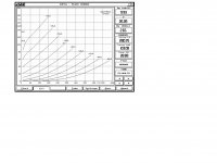
I like to re-itter something said: the static loadline with max power is given in the dotted curve of the first diagram, the 25W curve, DC conditions. Now, taking an operating point below that line, you can calculate how often the spontaneous transmission (nice word here) is going to be, for that, use a calculous of the
Just a remark: having worked with such PP amps, the 450V from the chart is the Vb, from that deduct the 30-35V cathode over the cathode resistor [One often forgets, I do at least], so the DC could be 420Volt anode-cathode.
- sine wave and what the length of time is the tube is in the above-the-line situation
- the programming material - how often do peaks occur (not much)
- the tube permissbible overload, as mentioned, TV-tubes are made for operating instantaneously 'above the line', repeatedly, without harm. As long as it is a very short period for everything to calm dowm.\
Just a remark: having worked with such PP amps, the 450V from the chart is the Vb, from that deduct the 30-35V cathode over the cathode resistor [One often forgets, I do at least], so the DC could be 420Volt anode-cathode.
One thing that is often forgotten is the class AB maximum dissipation. I know solid state folks are conditioned to keep the loadline inside the SOA for all instantaneous conditions (with good reason), but the only thing that applies here is the maximum average dissipation. Approximately B+^2/(2.5*Ra-a). Keep that (and the quiescent) under the max plate rating and all is fine. Once you take care of that, you need to keep screen dissipation under control. There is no easy way to calculate where that maxes out because that screen current is nonlinear and varies depending on a lot more things. You would literally have to do numerical integration on the Ig2 curves for the specific tube in question and operating conditions. And dont make the mistake of blindly trusting a spice model because you don’t know how well it matches secondary parameters like Ig2.
Thanks wg_ski, 3k5 Raa at 450V B+ is indeed still within the 25W max plate dissipation of the EL34.
I'd try the 4k with 23%UL and the 6k6 with 23% without any feedback and see what I like most: when I tested 6V6GT I've preferred 8k (more linear) over 6k6 (a bit of midrange prevalence).
Concerning the negative feedback I've proposed, I've found similar tests on solid state as well:
https://www-ne-jp.translate.goog/as...ch=http&_x_tr_sl=auto&_x_tr_tl=en&_x_tr_hl=ithttp://www.ne.jp/asahi/evo/amp/Dnfb/edc.htm
To re-explain the concept: standard nfb sends back a certain and fixed amount (ratio) of output signal (that is the input signal amplified plus the amplified error) in order to reduce the distortion, but this causes also the gain of the amp to be reduced, because you feed back a certain ratio of the amplified signal too.
This "distortion only" feedback (or Corr.Diff. as French call it) takes the output signal (that is the input signal amplified plus the amplified error) scaled down, process it in a differential amplifier together with the input signal, so that the output is:
Gain of differential amplifier x (input signal amplified than scaled down + error scaled down - input signal) = error scaled down and reamplified
This way I can apply only the error (distortion) as feedback, so gain of the stage is preserved until the error (distortion) is so big to nullify the gain of the amp.
You can find schematics in my previous link, I can post them directly here if you prefer.
Why stick with EL34?
Just because some guitar amps used them?...
I have a guitar amp that doesn't use EL34.
It's quite Marshall-esque. ( not much unique between amplifiers )
It uses 6L6GC in PPP.
There see a few folks that have used the amplifier circuit modified for hifi.
Not a huge mainstream amplifier, but Eric Clapton and The Police used one for a while.
It uses 6L6GC in PPP.
There see a few folks that have used the amplifier circuit modified for hifi.
I was merely alluding to other comments suggesting EL34 might not be the best choice.
For all I know neither is 6L6GC.
Nothing new under the sun, and all that.
Here is that same 6V6 PP Class AB2 Amp with Peter Gabriel Doing Salsbury Hill.Like this? Done with an analogue gate I built about 20 yrs ago.🙂
The blue trace is the PS sagging under load.😱
The blue trace shews the power supply volts bouncing as Gabriel hits it.
Attachments
What information would you like? Keep in mind this amp is experimental.
Class AB2 is usually not considered HIFI. One of the objectives of this build was to try Class AB2 both
on a limited PS, then on a stiff B+. For that I used my lab supply. All that gives a measure of headroom,
something manufacturers of low cost equipment rely on. As do guitarists.
NTL, under normal listening conditions it sounds OK.
What was the "ok" sound like, compared to an higher load?
During my tests I've always felt that low loads have a midrange hardness that is not present with higher loads.
This applies to Hi-Fi and instrument amplification as well.
During my tests I've always felt that low loads have a midrange hardness that is not present with higher loads.
This applies to Hi-Fi and instrument amplification as well.
“Midrange hardness” = increased IMD. Higher impedance loads with most tubes tend to reduce IMD, and require less drive, but drop the power of course. You use more heater power and screen current per amplifier watt with a higher impedance compared to a lower one, just another trade off you have to make.
And in UL there will be an optimum load for a given % tap and supply voltage. In regular pentode you can move the load line up or down and optimize Vg2 accordingly. Gives you one more knob to turn - if you’re not allergic to (global) feedback.
And in UL there will be an optimum load for a given % tap and supply voltage. In regular pentode you can move the load line up or down and optimize Vg2 accordingly. Gives you one more knob to turn - if you’re not allergic to (global) feedback.
Thank you wg_ski! Now I know what is in reality what I feel as hardness.
Thanks also for the hint on triode/UL/pentode configuration.
What I've found, and seems logic, is that higher % of UL make the power amp less sensitive to the optimum load, because the knee becomes softer.
Thanks also for the hint on triode/UL/pentode configuration.
What I've found, and seems logic, is that higher % of UL make the power amp less sensitive to the optimum load, because the knee becomes softer.
Yes"
What I've found, and seems logic, is that higher % of UL make the power amp less sensitive to the optimum load, because the knee becomes softer."
??
Please can you explain?
In attach the test with Sofia on EL34 UL connected.
Walter
Then ?
In addition, which is the optimum load?
When in the real world the Zload is always varying with frequency?
Walter
That is the Real World, something a knowledgeable designer anticipates.
The tests on the final finished amp need to be a lot more than 'how does it sound'.
That means making an investment in reliable test equipment.
And the time taken to understand the results of the tests, something many fail to do.
Simulations are only a start.
The tests on the final finished amp need to be a lot more than 'how does it sound'.
That means making an investment in reliable test equipment.
And the time taken to understand the results of the tests, something many fail to do.
Simulations are only a start.
Hi jhstewart9, I do not pretend to be a knowledgeable tube amp designer, but to learn something new every day.
I'm a Mechanical Engineer and I design processing for the beverage, so a totally different field.
I already have a signal generator and an oscilloscope, but I'm moving to a new house and I don't have a dedicated room for them at the moment. If you don't like the "how it sounds" question, just report what you think it's useful to know about it.
Thanks.
- Home
- Amplifiers
- Tubes / Valves
- Lowest safe loadline: what is the limit?