ARTA looks interesting. But doesn't replace what I'm using now.
Looks like the BW is rather limited. And audio output level limited as well.
But might be interesting to try sometime. Maybe later.
Lots to do here aside from DIY. Today I spent a couple of hours
on a tractor pushing snow.
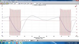
This pulsed One KHz at +15 Watts run on a PicoScope 3224 running driver
r6.8.8 on an olde HP laptop loaded with WIN XP Professional.
The blue trace shews B+ dropping almost 6V delivering that power to
the 7.5R load on the H125E OPT.
I've also got the Pico Driver running on a Dell with WIN 7 Prof.
The drop in the HT depends first of all by the power trafo and its Rdc, then from the reserve of Joule on the bank of capacitors.
In addition, last but not least, around the Z of the OT trafo.
If you are conservaitve, in the real world, a change of Z due the real load doesn't move a lot.
In my post 36 there is a dinamic test, rms and impulsive.
The results show the capacity of the amp to deliver current also for a lower load. The curve drop at low Z
In this case the cap bank are 8 x 470 uF /550 Vdc ( the HT operative voltage is 510 Vdc) each amps and the voltage stay fix
Regarding the Arta the BW is large nough to understand the circuit, the with the interface from Millet you can manage a large signal.
Rgearind the signals REW has what you want , look also for Sinegen, VA, Spectralab.
Walter
THX for your vote of confidence. Many folks are happy with an indication of THD at One KHz in a resistor load.Excellent set of equipment and battery of tests, jhstewart9. Good on you too for actually implementing it. I will incorporate some of the multi-tones in my tests in the future.
I found the varying H3 levels you mentioned intriguing.
That doesnt tell us much about what will happen in the real World. So having built many audio amps & a variety of
TE, here I am. Much of what is available today was impossible when I started.
So being inquisitive makes a lot of sense & leads us down many paths. My career was totally hitech from the beginning.
And included a 3-year stint in the Electronic Distance Measuring buz at HP. For a time we sold EDM to Surveyors
& Civil Engineers. I got to go to work in jeans, safety boots & a hard hat. And travelled extensively for 45 yrs.
Both HP & R&S were cornucopia of very advanced concepts. As was IFR/Aeroflex & Boonton. Lots of ides to
keep us busy.
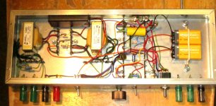
So in my free time I built this Burst Gate, not like people would think. An RF Engineer would see a Balanced Modulator.
There are better ways to do this. But I built this & got the information I wanted. And able to present it here.
Most folks don't shew any results of tests here at all. Everything 'Sounds OK'.
Attachments
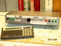
Does the Burst Gate allow checking the transient recovery behaviour?
That's the kind of thing I am interested about and often scratch my head at testing with sines at 1K only too. There's a massive amount of information in transients that we should test for more in depth and more often, IMO.
I am going to re-use that wire-as-brace technique too - ingenuity, a trait common to all Engineers.
I think Norman Crowhurst did some work on that. I'll have a look in a few days.Does the Burst Gate allow checking the transient recovery behaviour?
That's the kind of thing I am interested about and often scratch my head at testing with sines at 1K only too. There's a massive amount of information in transients that we should test for more in depth and more often, IMO.
I am going to re-use that wire-as-brace technique too - ingenuity, a trait common to all Engineers.
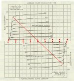
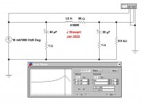
Here is a good way to determine optimum load for PP Pentodes. This is set for a 400V plate supply.
The slope of the loadline depends on the Screen Supply Volts.
Unfortunately that is not published for many audio tubes. But there is plenty of data for TV Sweep Tubes.
For audio I set the loadline somewhat steeper to allow for the impedance variation of the loudspeaker vs Frequency.
Some researchers claim this also reduces 3H somewhat.
Obviously only one half of this image is required to get the answer.
Just looks impressive, as in an EE Text Book!
Attachments
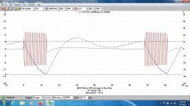
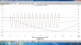
Tests on a 25W amp of traditional design. This time PP UL 6L6GCs, 450V on the plates, 80 mA plate current.
The PS is a Hammond 273BZ 350-0-350 running thru a 5V4GA, but originally a GZ34.
The filter section is a CLC, 40/1,5/35. The filter is resonant at 21.8 Hz.
Both SMPTE & Pulse tests were run.
How would your favorite amp look running theses tests?
The PS is a Hammond 273BZ 350-0-350 running thru a 5V4GA, but originally a GZ34.
The filter section is a CLC, 40/1,5/35. The filter is resonant at 21.8 Hz.
Both SMPTE & Pulse tests were run.
How would your favorite amp look running theses tests?
Attachments
-
 3W Pulse.jpg174.8 KB · Views: 84
 -
 20W Pulse.jpg178.5 KB · Views: 91
 -
 40W Pulse.jpg159.7 KB · Views: 82
 -
 40W Pulse C 2 mS div TB.jpg161.4 KB · Views: 79
 -
 PS B+ Ripple.jpg130.9 KB · Views: 80
 -
 SMPTE One Watt 80 Hz & 5 KHz B.jpg162.5 KB · Views: 72
 -
 SMPTE 10Watt 80 Hz & 5 KHz.jpg170 KB · Views: 66
 -
 SMPTE 25Watt 80 Hz & 5 KHz.jpg174.7 KB · Views: 73
 -
 25W Amp PS Resonance.JPG31.9 KB · Views: 78
 -
 6L6GC UL Amp 1960 7.jpg47.2 KB · Views: 92
 -
 IMG_6445 to 6446 Test Bench 16W 20C.jpg504.1 KB · Views: 85
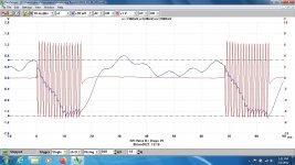
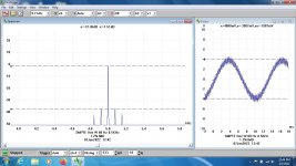
Here are a couple of multitone tests I did on my 40W transmitter tube SE amp. Both are at 1W output.
I'm inexperienced at figuring out what they reveal, but the amplifier has amazingly low distortion with 1kHz sine waves. My best result at 1W so far is .015%.
I'm inexperienced at figuring out what they reveal, but the amplifier has amazingly low distortion with 1kHz sine waves. My best result at 1W so far is .015%.
Attachments
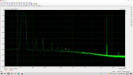

Both spectrum's look like 0.1% D% But the 2nd spectrum shews what looks like PS, 60 Hz & Harmonics.
What make/ model of analyzer are you using?
What make/ model of analyzer are you using?
There could be a ground loop in your measurement setup that would cause that 60 Hz & Harmonics.
Sometimes these are difficult to find, causing lots of problems.
Sometimes these are difficult to find, causing lots of problems.
I'm using ARTA software on a laptop computer with an M-Audio M-Track Plus II USB audio interface, along with the interface box designed by Pete Millet.
The second spectrum was only 18k and 19k tones, so all of the LF stuff is grounding issues. It is present in the first, but there is a 60Hz tone on top of it.
The DUT is a somewhat messy breadboard amp that went through lots of iterations and reorganizations (I mean, it started out neat). I'm sure I can improve the grounding a lot and eliminate ground loops when I build the actual amp. I'm still evaluating general approaches.
Often the grounding issues are not in the equipment at all.
They occur in the external circuit between separately powered devices that are connected together.
I've seen plenty of that. The broadcasters have avoided ground loops by using 3-wire hookups
& high quality audio transformers on the ends of the signal path.
A differential amplifier front end is also helpful.
In the case of this amplifier, the ground scheme is not well executed. I'm pretty certain that it is at least a significant contributor to those humps. I just don't want to focus on it yet until I settle on the topology. I have four teen daughters and so my circuit playtime is quite limited. 😉

Here's the same amplifier distortion result @1W with a 1kHz sine wave.
In my push-pull amp I finally just used some Jensen input transformers. I just couldn't get that slight buzz to go away completely any other way.
Here's the same amplifier distortion result @1W with a 1kHz sine wave.
In my push-pull amp I finally just used some Jensen input transformers. I just couldn't get that slight buzz to go away completely any other way.
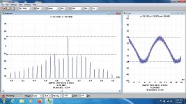
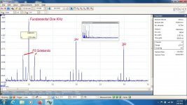
With your SA is it possible to magnify the detail at One KHz?
I think the PS sidebands are riding on the One KHz.
Easy to see on the PicoScope SAs I'm using.
My family flew away many years ago. Now I spend time with a chain saw & tractor.
Not too much snow here yet, but each year lots to do. The property is 4.4 Acres (2 Hect).
Lots of firewood.
I think the PS sidebands are riding on the One KHz.
Easy to see on the PicoScope SAs I'm using.
My family flew away many years ago. Now I spend time with a chain saw & tractor.
Not too much snow here yet, but each year lots to do. The property is 4.4 Acres (2 Hect).
Lots of firewood.
It probably is possible to magnify. I haven't tried it, but I think you are right that those little horns are the PS intermodulation. I'll try zooming in next time I test.
How many bits are the DACs on the PicoScopes? How much dynamic range do you get out of them?
I just finished helping my parents split all of their firewood for the winter. I took the kids along and kept them busy. We don't do much wood splitting for ourselves here in Southern California.
How many bits are the DACs on the PicoScopes? How much dynamic range do you get out of them?
I just finished helping my parents split all of their firewood for the winter. I took the kids along and kept them busy. We don't do much wood splitting for ourselves here in Southern California.
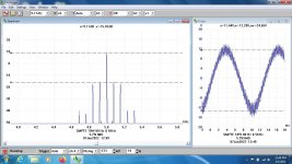
This screen was run using a PicoScope 3224, 2-Channel, 10 MHz BW.
It is 12-bit so 72 DB is theoretically possible, 60 db is 0.1%, good enough for most tube applications.
This time I first ran at relatively low frequency resolution for a quick picture. The result is an average of 32 measurements.
Then bracketed the area of interest & ran that at higher resolution. The PS sidebands are clearly visible.
Averaging improves resolution & reduces noise by the square root of the number of samples in the measured group.
The amplifier in test is another of my oddball ideas. It runs a pair of 33s in Class AB2 UL.
The Driver is another 33 triode connected. The front end a 1B5. All 2V filament tubes
I've another PicoScope that is 16-bit but seldom use it.
Attachments
- Home
- Amplifiers
- Tubes / Valves
- Lowest safe loadline: what is the limit?